---------- Forwarded message ----------
From: John
Date: Fri, Dec 2, 2016 at 12:56 PM
Subject: Verrry interesting...
To: JtC
Yo!
This morning I swapped the fuel pump relay with one of the thermo fan relays and gave it a start. Buzzing as usual. I thought I would check fault codes...
Don't know B2aaa, but I think "B" is something to do with body control module (which is deleted). I know the low-speed thermo fan function is managed by the BCM, so there is every chance it is tied-in with P0480.
Entered a custom sensor ID for the oil pressure into the OBD2 scanner last night. Tried it this morning... no good. Will keep trying.
Read the fault code log. There were a few there. I cleared the log, then checked again and nothing resurfaced, so it looks like the sensors we are no longer using (e.g. post-cat O2 sensors) have been switch off. I'll keep an eye on it.
Doing a bit of research (e.g. http://grego.ca/limp.htm), a TPS fault is treated REALLY seriously (which makes sense as the computer can't reliably know where the throttle blade is).
And I quote...
"When this code is stored, the PCM will usually enter limp in mode. Engine acceleration will be severely limited (if not disabled) in this mode".
Here's hoping that clearing that fault will be the simple fix to the lack of power!
Yesterday's efforts broke the back of the last leg to start-up, with the only remaining wiring being the interface with the existing Chev circuits:
- wire ignition on (pink 4mm wire).
- wire into the brake circuit (red 2mm wire).
- wire the reverse lights (yellow 2mm wire).
Then it was a case of adding all fluids, holding our collective breath and turning the key!
Nothing.
With "ignition on", we could hear the fuel pump relay click and the fuel pump whirr into life for a couple of seconds then stop. All good. Part of the design.
Then twist to start, we could hear the starter relay click, as well as a loud clack from the starter solenoid... but nothing.
After a couple of twists with nothing, one last twist caught and the engine stumbled into life...
A couple of things... you can hear some lifter tap, so there was a bit of concern around oil pressure. The idle is rough and hunting, plus the accel pedal did nothing.
We killed it and scratched our heads for a while; we needed to know what was going on.
I took a drive to a mate's house (Stu the Aussie champion) who lent me his OBD2 ELM327 adaptor. But on my return, JtC had nailed it!
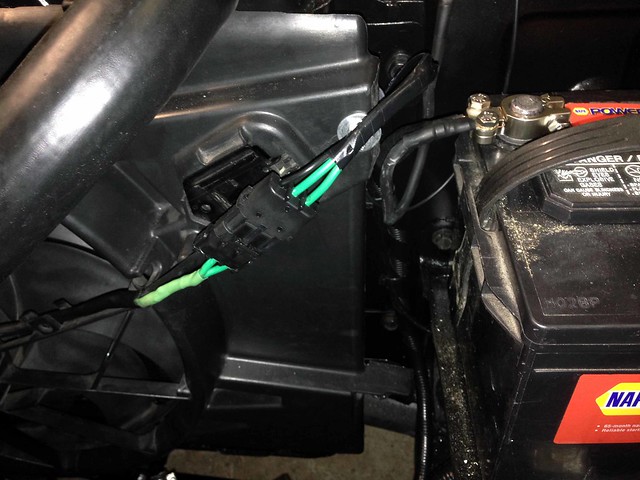
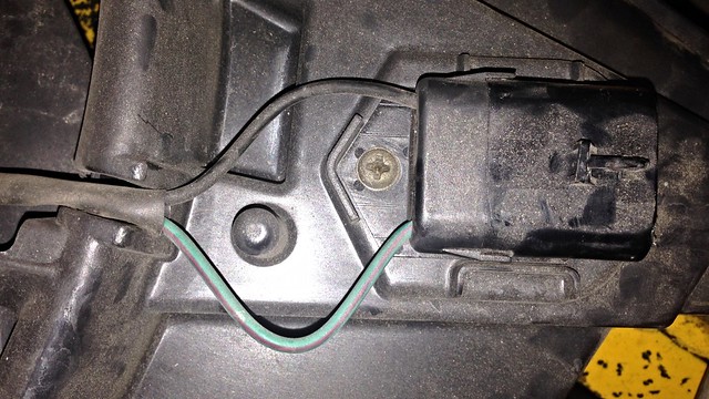
The plug to the throttle butterfly was loose. A quick click and voila! Smooth idle!
We even had gears. First time in daylight for nine months...
A quick run up the hill showed that the thing was gutless as anything. Full throttle saw the car crawl up the hill... something awry there.
And one final issue, a buzzing from the relay that feeds the fuel pump...
One final video that highlights the baulk on start. The first crank is a no-go and the second fires...
So the issues are:
- baulks intermittently on start-up
- buzzing fuel pump relay
- gutless
Interestingly in the last video, the fuel pump relay is much quieter.
Time to do some research but the issues do not seem insurmountable.
HUGE thanks to JtC for all his efforts! There is no way I could have achieved all this in the time we did without his time, efforts and experience. Well done!
Through the week I booked the exhaust for 9/12 and rego inspection for 12/12, so there is a real urgency now to knock-off the last items on the to-do list... the majority being related to keeping smoke within wires.
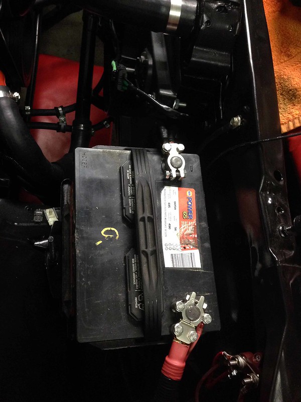
We had mini working bee Tue night to fit the battery tray and drill through the firewall on the passenger side for battery positive, thermo fan and starter wires.
During the week, various parts were acquired ready for a committed weekend of wiring...
- 25 mm2 cable (battery to starter, batter to alt, ground)
- lugs for 25mm2 cable
- distribution post for feeding battery +ive to various circuits
- relay base (will reuse a relay from the VZ for P/N start conditioning)
- plug for thermo fan connection
- 10mm dia split conduit
- 16mm dia split conduit
So to the weekend: a HUGE double header from JtC, making the trip north on both Sat (wiring till midnight) and Sun in an attempt to get the beast started.
First mission:
- Create new battery/ground cables.
- Wire the battery positive/starter/alternator/ground harness.
- Wire the existing Chev battery positive harness to the existing horn relay.
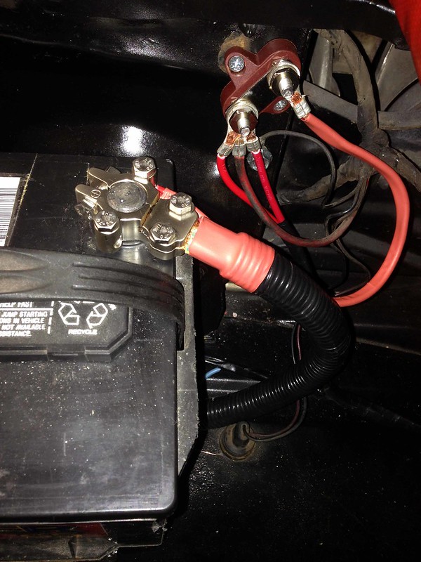
- Wire constant power source (red 2 x 6mm wires) from EFI to battery positive...
Detailed shot of the battery +ive distribution post arrangement...
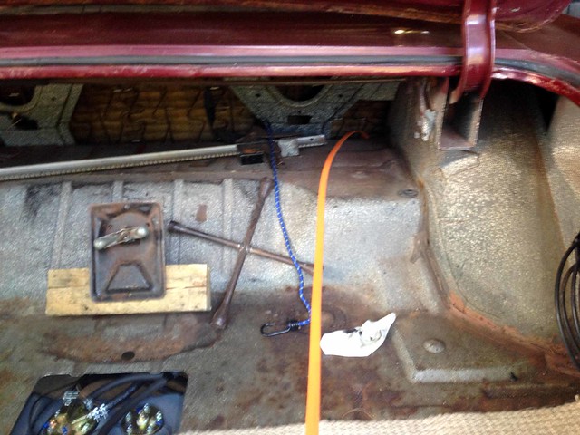
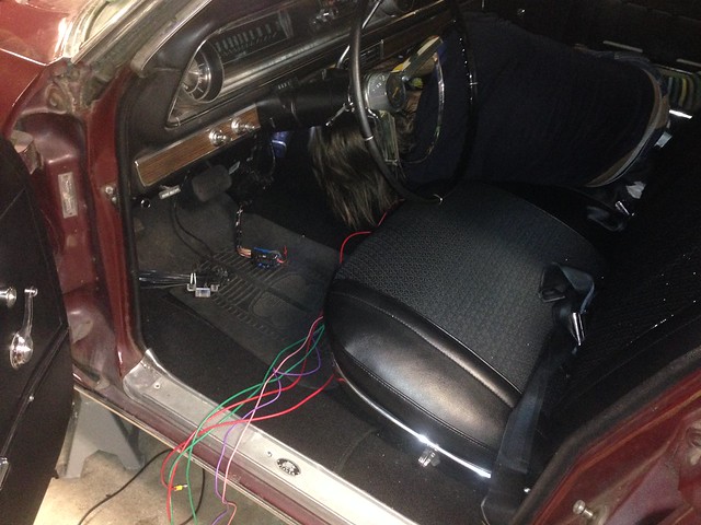
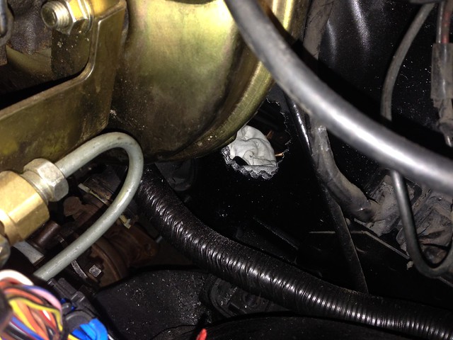
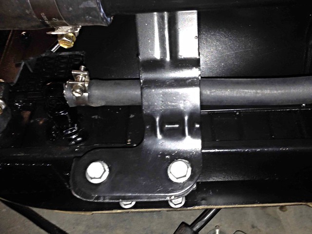
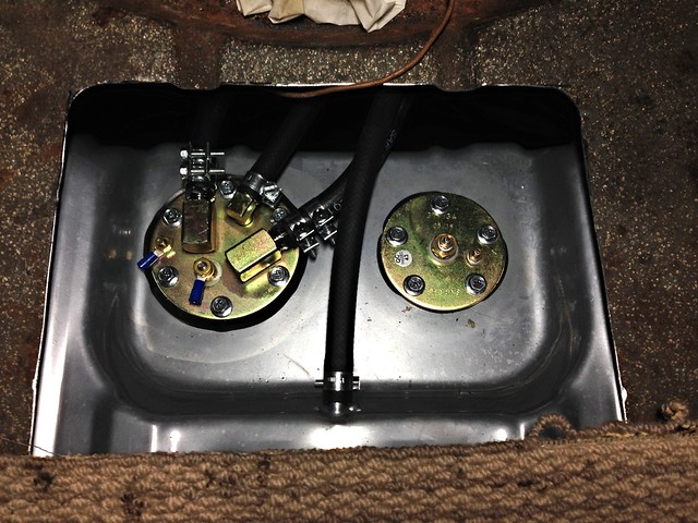
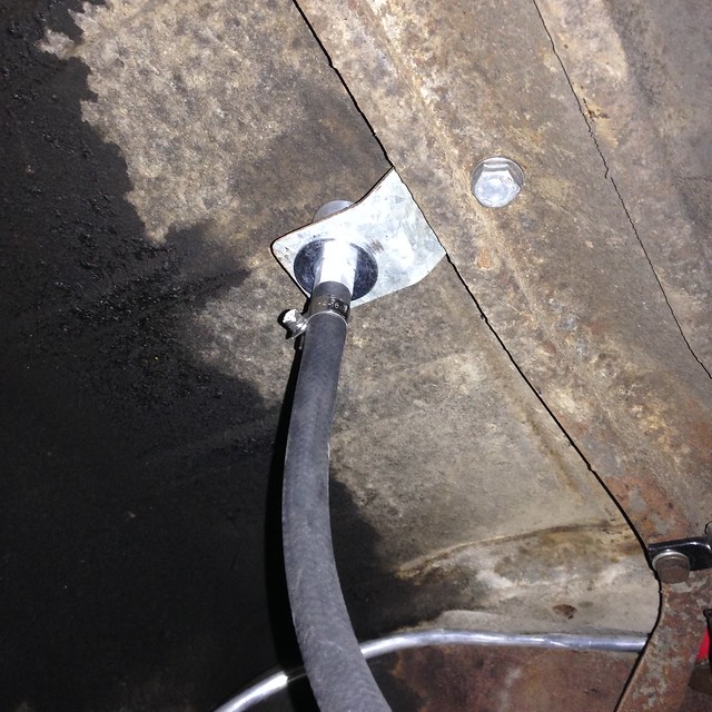
Secondly: Wire the fuel pump (purple 4mm wire). We ran the wire under the carpet (down the passenger side of the car), under the base of the seat and dragged it though into the boot using floor board tongue...
From there we passed it under the car, through a re-purposed grommet (that was used for the old fuel tank vent), up to the fuel pump and terminated.
Third task takes place under the dash (hard to take photos as the wiring is so well hidden!):
Wire a starter relay which is conditioned to feed the starter solenoid only when the trans is in Park or Neutral (managed by the ECU... the existing Chev P/N switch is by-passed).
We grabbed a relay from one of the VZ relay blocks and mounted into a relay base that clipped to the end of the string of relays in the ECU harness.
existing Chev start trigger wire = pin 86
grey 2mm wire from ECU = pin 85 (switched ground).
existing Chev start trigger wire = pin 30 (looped from the feed to pin 86)
wire to starter solenoid = pin 87
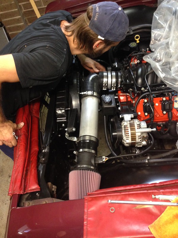
Fourth: Wire the thermo fan (green 2 x 5mm wires).
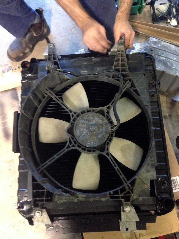
The most annoying work is having to do work a second time. This was what was before us in having to remove the Commodore thermo fan and start the mounting process from scratch with the Falcon fan.
JtC made the trip up and got stuck in.
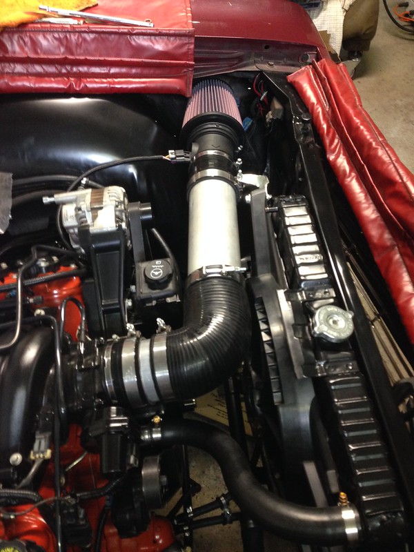
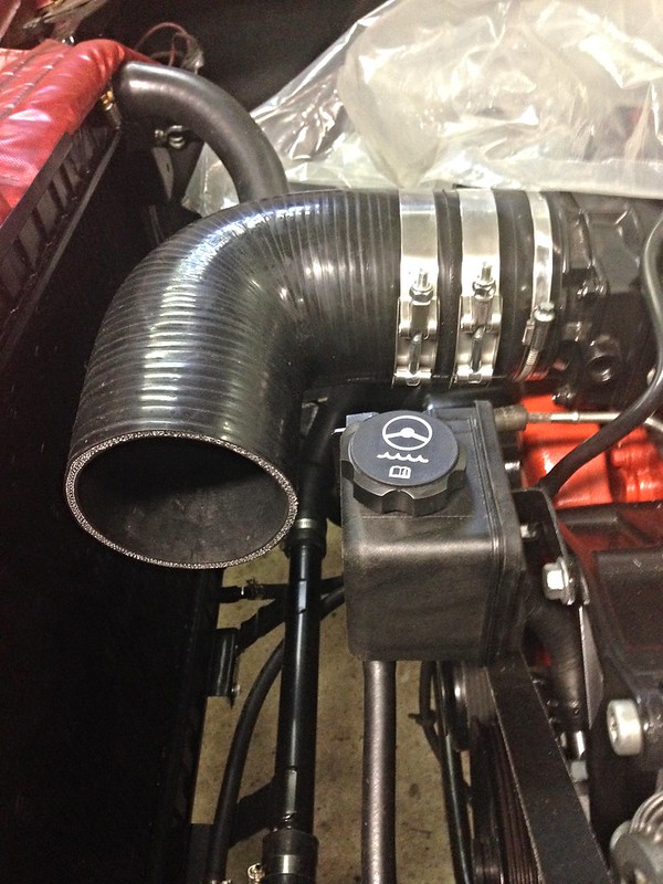
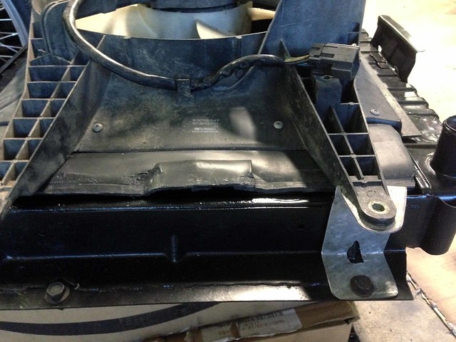
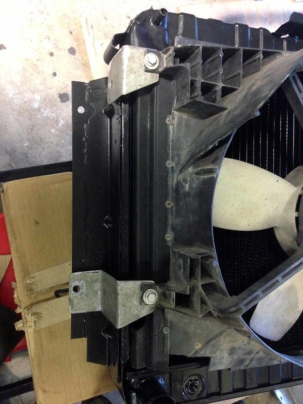
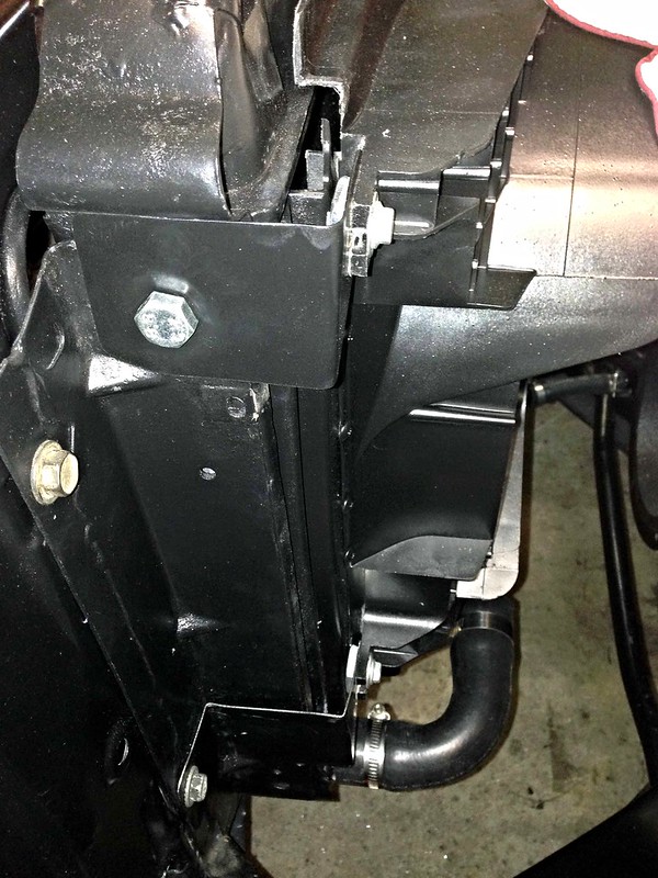
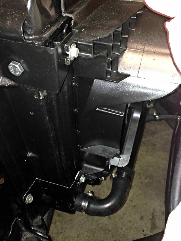
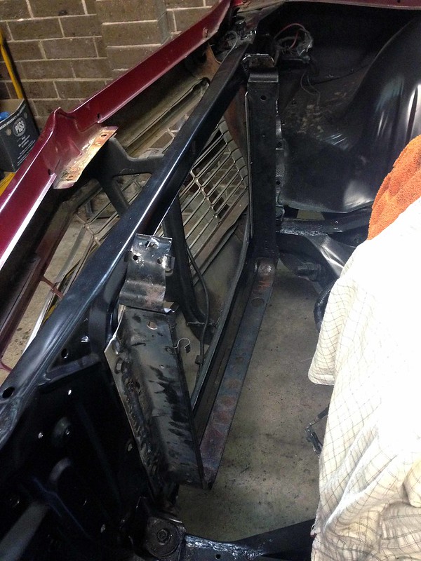
Thankfully, it was more material removal required than making a shroud. The Falcon fan sat well, hard against the radiator core with a slim profile, allowing the intake pipe to thread its way between the radiator and the power steeering reservior...
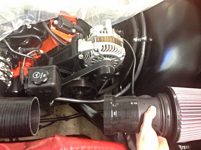
The MAF/pod filter assembly is supported and held in position by a bracket off the radiator support.
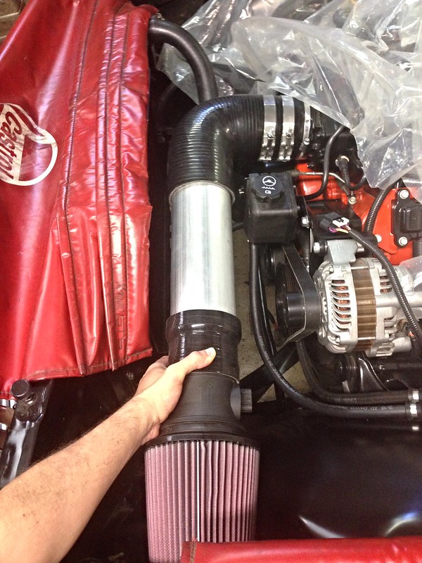
Note the exposed length of alloy pipe at the throttle body inlet.
Clearance everywhere... a work of art!
BIG thanks to JtC in enduring the pain of doing a task twice-over, all the while taking his time to do it right!
J
P.S.
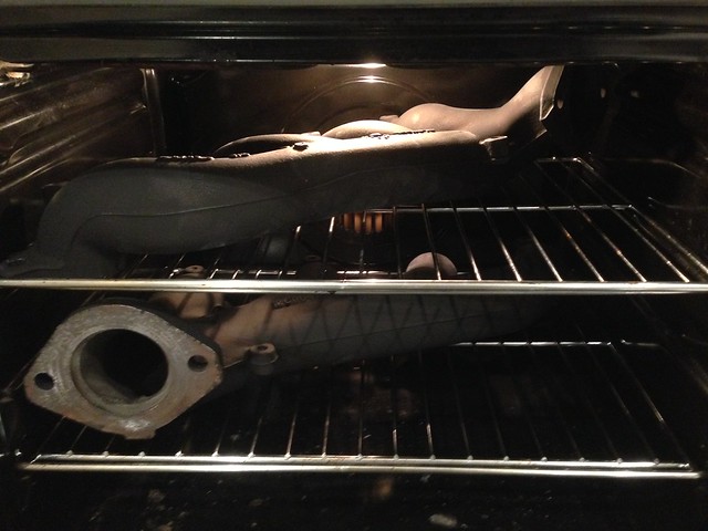
While inlet + thermo fan was happening, I wire-brushed and painted the battery tray ready for refitting.
P.S.S.
The photos above were taken before the steam pipe was connected, but JtC connected it as well <phew>!
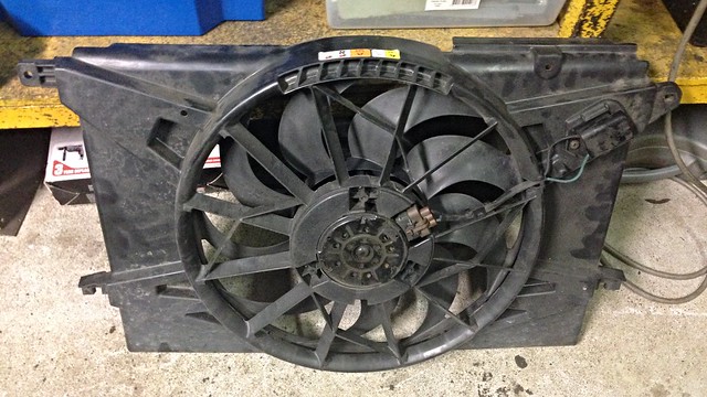
So the original plan to use a thermo fan from a VS V6 Commodore (see here) wasn't going to work.
Once we started dummying-up the intake, it soon became obvious that the massive shroud over the top of the VS fan was going to foul the pipe to the throttle body.
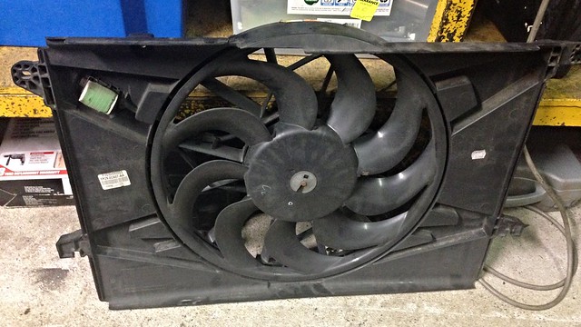
After a bit of research, it was decided to go with a thermo fan from the dark side... a big single from a FG Falcon...
Short piece of silicon hose and alloy pipe off the throttle bode to ensure the 90 degree bend could clear the power steering reservoir.
The more astute reader will notice the missing radiator fan.
Clearing the power steering reservoir meant the huge shroud of the V6 Commdore thermo fan we had installed a couple of weeks prior was now going to foul the intake <sigh>.
Solution to that little issue next post.
The good news is the top radiator hose I sourced here, worked a treat (with a bit of judicial trimming)!
Trialing the MAF/pod position...
Dummied-up...
This will be the final position of the pod/MAF, with some tweaks to be made to the reducer section length (4" section too short... swapped for a longer one), and exposing some of the alloy pipe at the throttle body (by reducing the 90 deg. bend leg length).
After much umming and ahhing over the decision of where to mount the engine ECU + gearbox ECU + associated relays and fuses, the decision was finally made to make use of the existing hole in the firewall, set aside by GM for the clutch master.
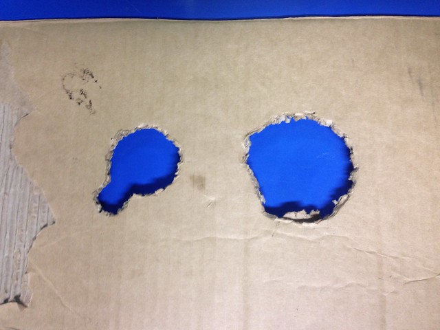
It was around 2" diameter, so a cardboard template was cut-out to practice pushing the large ECU harness plugs through...
The first hole was an experiment in leaving the orginal firewall hole diameter and cutting a recess off to one side to house each strand of the harness as we passed it through.
Good in theory, but no cigar... 2" diameter was too small.
On the right is a 3" diameter hole which worked fine.
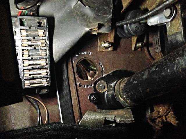
Time to get cutting...
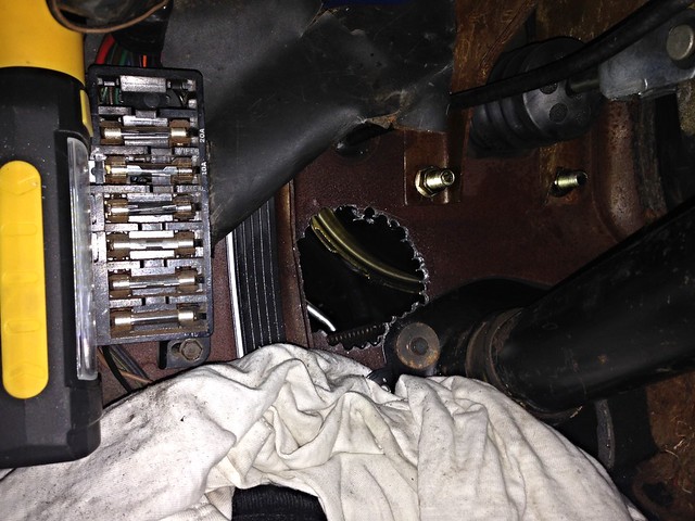
Getting bigger...
Once drilled-out, all jagged edges were tidied-up with a carbide burr on a drill and lined with a grommet made out of spilt ATF cooler hose.
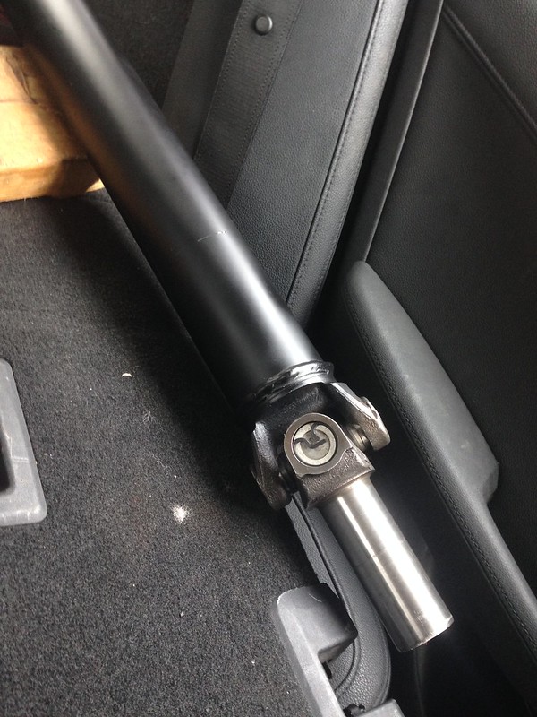
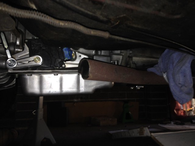
New thicker-wall tailshaft (80 mm shorter than original to accomodate the longer 4L65E) and new uni joints, packed with grease ready to be bolted-up...
Work done by A&L Driveshafts in Campsie.
UPDATE: exploded on the dyno on Tue 17.04.2018.
The A&L driveshaft was 2.750" OD with 0.083" wall... waaay too small!
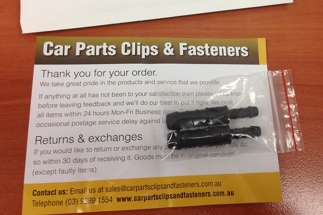
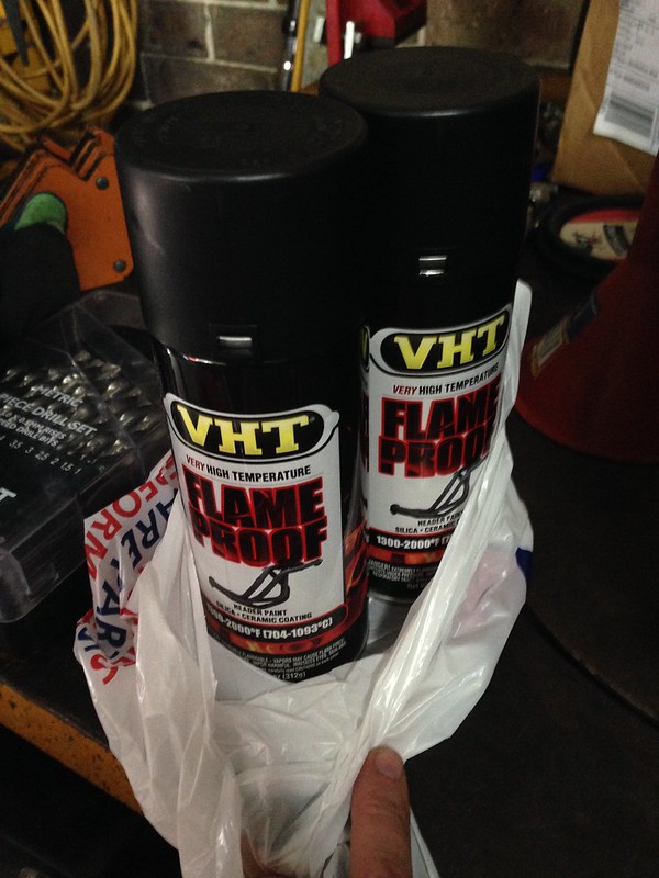
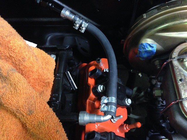
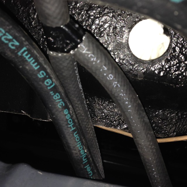
The steam pipe outlet on the LS needs a 6 mm ID hose.
The inlet port to the top tank of the radiator needs a 10 mm ID hose.
Get both size hoses and join in the centre with this...
One required but bought two in case one snapped ;-)
---------- Forwarded message ----------
From: John
Date: Tue, Oct 18, 2016 at 11:00 PM
Subject: CSI: Radiator Hose Unit
To: JtC
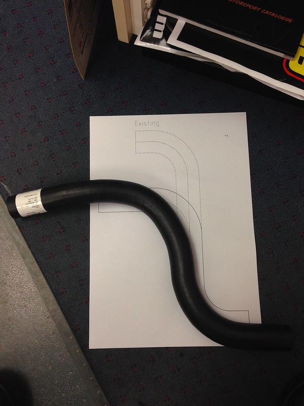
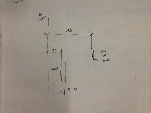
1.
After a bit of measuring down in the garage, the attached "Top Radiator Hose Drawing" is going to be in the ball-park of what we are looking for. Printed out on A3 will give me a 1:1 template I can take with me to a parts store.
2.
Mackay Automotive have put out an AWESOME catalog which lists their hoses by ID, then length...
BIG weekend spent on the Chev... and another BIG effort from JtC!
Saturday started with choosing a thermo fan from the pool of fans (what is the collective noun for electric thermo radiator fans?) we had lying around the place.
We settled on a VS V6 Commodore fan; will it draw enough air? We'll see! At the very least we put 12V across it and it certainly works.
Time to fabricate a shroud and get it mounted. Scavenged plastic sheet from old radiator shrouds and self-tappers FTW!
Folded gal steel sheet was used as bracket material, salvaged from a bash/splash plate from the underside of the VZ ute...
The shroud and brackets were hit with satin black in the evening, ready for Sunday.
A new day and new challenges.
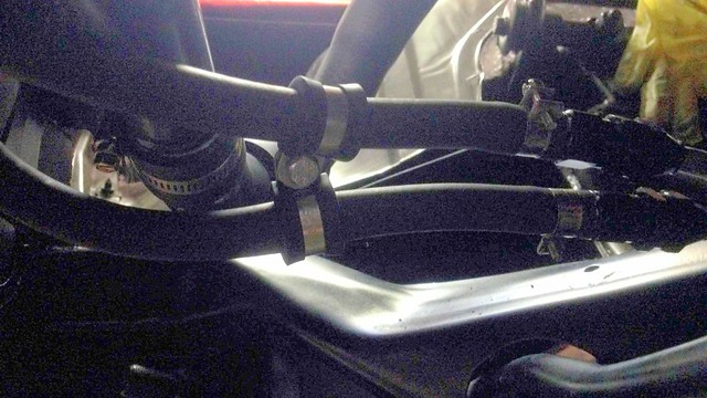
The bottom radiator hose arrangement was adapted from the VT II/VX/VY setup we used on the test frame. This meant:
U-shaped hose out of the water pump (Mackay Rubber part number CH2956),
VT II/VX/VY transfer pipe (sourced second-hand from a wrecker) and
90 deg. hose into the radiator (Mackay Rubber part number CH3028... cut-down for the narrower Chev radiator).
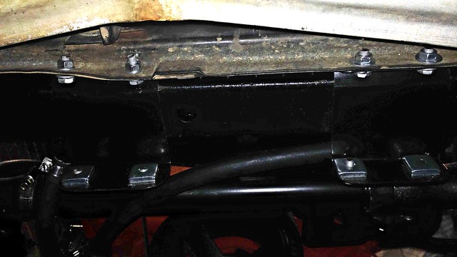
The transfer pipe has mounting tabs which we bolted to the radiator support panel using more brackets fabb'ed from the VZ splash plate material. Bit dark, but it's there I promise!..
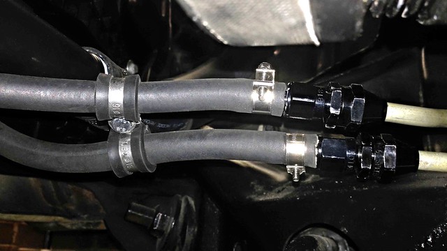
The last photo also shows the ATF cooler hose sitting on top of one of the transfer pipe brackets. The cooler hoses were connected to the radiator using Speedflow fittings/barbs and standard ATF cooler hose, retained with hose clamps. Might swap to hose with AN hose ends in the future when the wallet recovers.
More ATF cooler hose goodness...
Finally, the finished product...
Massive thanks once again to JtC who did the majority of the work; excellent workmanship yet again!
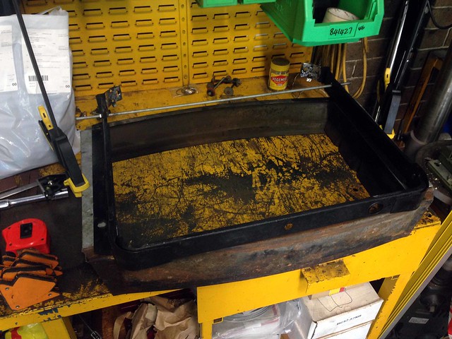
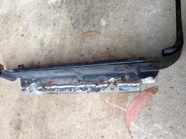
With the radiator left getting modified, I took the mounting strap/flanges home to be modified to mount the Chev's radiator support panel without using the spacer.
The spacer was a handy template, obviously having the bolt patterns for both the existing radiator mounts, as well as the radiator support panel.
Without the radiator to hold the correct bolt spacing, I bolted the support strap to the inside of the spacer and use threaded rod to hold the two sides at the correct spacing.
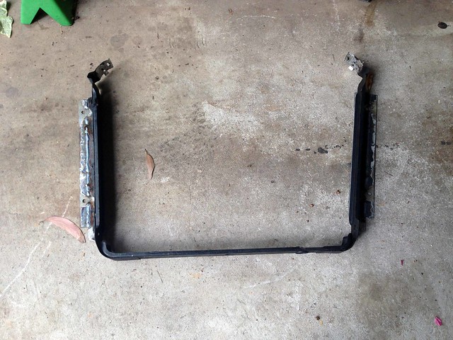
Then flip over the spacer and determine the width of flange required. Here it is with the flanges already cut out of galvanised steel scrap...
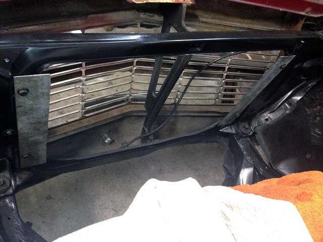
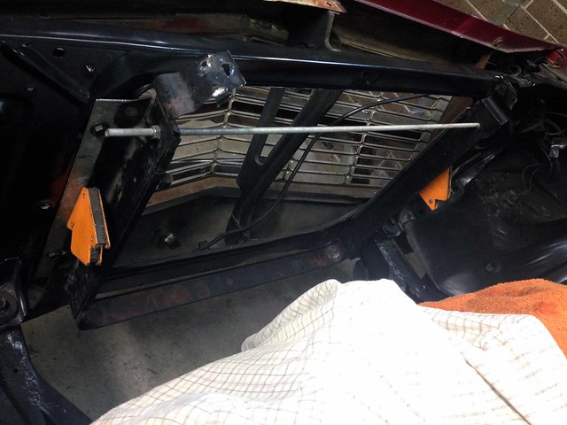
Holes were drilled in the flanges to match the radiator support bolt spacing, then bolted into the car...
...before lowering in the radiator mounting strap, locating it against the flanges in the final position and marking where the welds were to go...
Then it was time to break-out the welder!
Trial-fit in the Chev... all good!
Then a quick dress of the welds, prime and paint with satin black (no photos).
Now to drop the modified mounting strap off to Merrylands Radiator so it can be reunited with the modified radiator.
Stopped in at Merrylands Radiators this morning and explained the plan.
Ray was all good and will put Commodore-sized ports as far in the corners as possible, plus add the little steam vent port... all for $100! And could be finished this 'arvo!
He was just a bit unsure about the wider mounting flange so came up with the idea in the photo. Within a couple of minutes he had melted the solder holding the mounting strap and whipped it off the radiator. Now I can take the mounting strap home and weld a wider flange to it. He will remount it, all included in the $100.