Monday 30 May 2016

Ancillary Drive (the devil is in the details)

The VZ Commodore power steering pump had the inlet pipe pointing in the wrong dimension.

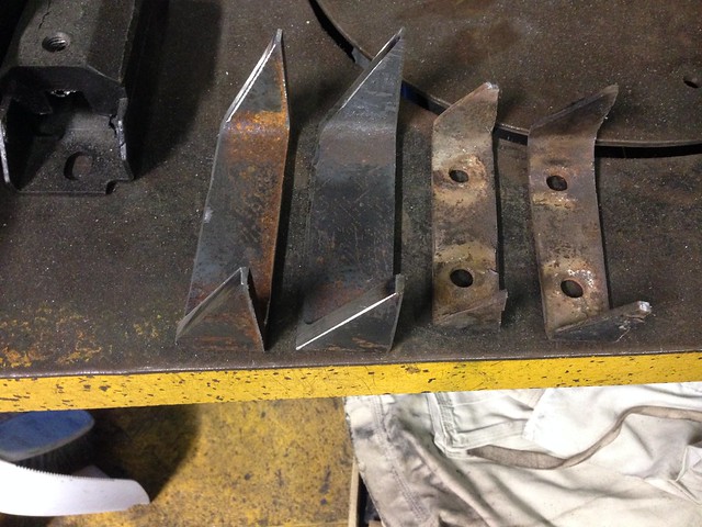
Originally the plan was to try and bend/twist the inlet pipe but too hard in the end.

Plan-B: source a new inlet pipe.

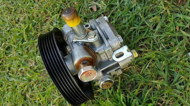
The KYB make of power steering pumps have an inlet that pushes into an o-ring and is held in place by a keeper plate. From various photos throughout the web, it looked like KYB standardised on the pipe diameter/keeper plate arrangement and simply changed the direction the pipe was bent to suit the vehicle it was going into.

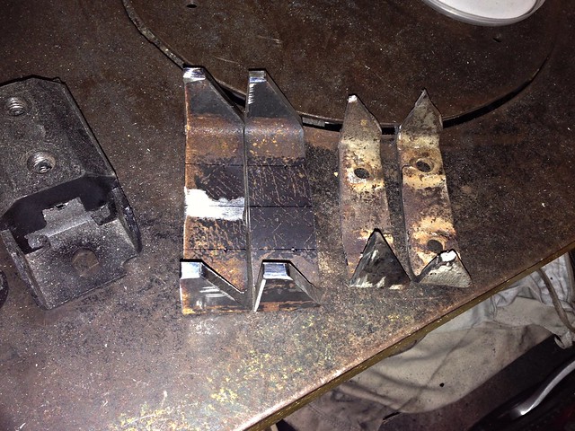
After a bit of a dig through photos and visiting the wrecker near work with a set of verniers, I went for a second hand Hyundai unit from eBay.

The inlet pipe was duly unbolted and - thanks goodness - has an identical mounting arrangement to the Commodore's!

It was soon bolted to the Commodore pump and dummy-fitted to the ancillary drive bracket...

Hyundai Pump 03


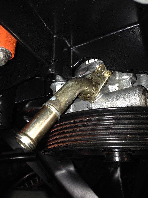
So the orientation of the inlet is MUCH better. You can see in the photo that the relief in the bracket sits hard against the keeper plate bolt. The angle grinder came out and five millimeters was quickly removed.

Went ahead and bolted the alternator, idler pulley and tensioner into place. Juuust managed to get the Commodore drive belt on (need to get a longer one) with the tensioner at the extremity of its travel...

Hyundai Pump 04

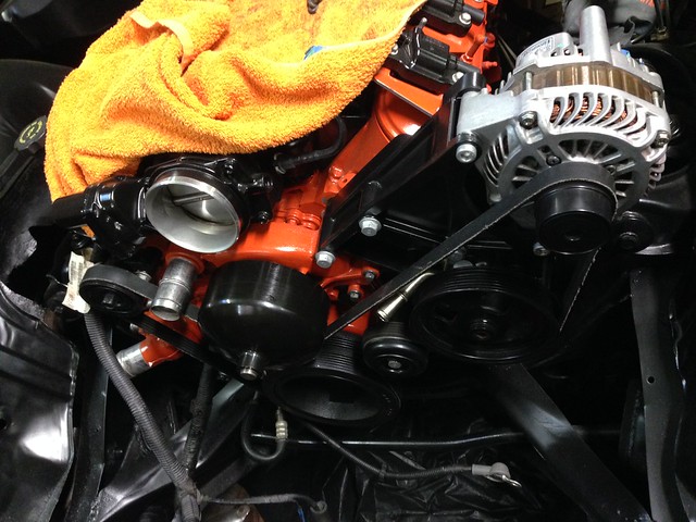
Evident in the photo above, the power steering pump inlet peeks out between the belt and the power steering pump pulley.

It is all a bit tight for my liking so time for Plan-C, enter one Mitsubishi Lancer power steering pump...

Lancer_PS_01

Here the inlet is vertical into the pump, so no belt clearance issues (I hope!).

I pick it up next week, stay tuned.

J

Wednesday 25 May 2016

Transmission Crossmember - Part 2

So, new on the left, old on the right...

Saddles 01

Saddles 02

The material is some scrap 125 PFC (parallel flange channel), pretty much perfect for my application!

The only downside is the PFC has very thick flanges (7.5 mm thick in this case). The nice part is that the web is 4.7 mm thick which is gold...


Welding to the chassis rail will be a bit interesting. I'll grind a bevel weld prep into the flange and do some test welds first to get the current setting right.

J

Thursday 19 May 2016

Transmission Crossmember - Part 1

Buzzed the trans mount tongue off the tubular cross member last night at 9:30 PM (sorry neighbours).

Unbolted the weird 90 degree bracket from the transmission mount, so now we have clear access behind the trans mount (attached is a photo).

The cross member can sit up under the snout of the trans, right where the axle stand is in the photo...


This would mean relocating the chassis saddles rearward to the tune of 200 mm.

We will need to lift the end of the trans 13 mm to get the tubular cross member under the snout. If my calcs are correct, it means reducing the angle of the engine/trans by one degree.

Should be fine. Now it is a case of checking the trans and diff angles, plus whether raising the end 13 mm fouls the transmission tunnel anywhere.

J

We may be able to reuse the existing crossmember, but would need to remove the black bracket off the trans engine mount.

It would be close re. exhaust.

What I might do is trim off the existing Powerglide mounting bracket on the crossmember because we need to change/relocate that anyway. Then I can lift the tube into place to see how it looks.

J

On Wed, May 18, 2016 at 10:51 AM, JtC wrote:
I am very keen to retain the x-member as-is, no mods if possible. Factory is always best & it's a nice looking thing.
Will the new gearbox mount drop into the old crossmember without any of it fouling on the curves of the xmember?
Will the dips for the exhaust still provide clearance in the correct places also?
Can we get the driveline angle right with the old Commodore mount arrangement? I think it's in two parts, we may just need to remove one part.
Sort out new handbrake cable situation. We actually needed to do that anyway.
I honestly think we will be able to simply relocate the old xmember forward/rearward as needed and then fiddle around with the mount height as needed with a little chopping and maybe a spacer or whatever.
From: John


The easiest method will be to relocate the existing chassis rail mounting saddles.

J

Saturday 7 May 2016

Stuff

Sat was two hours spent mucking around getting the Chev up on stands. Pain of a job with the engine pipes getting in the way of everything to do with the trans. All good now and spent the time getting a setup which has good access. I turned the front wheels to help the passenger side engine pipe clear the steering link, then brought the chain block over and used fabric slings under the engine pipes to lift them up, it has worked really well and we now have a clear floor under the Chev. I have sat the end of the trans on one of my old ratchet stands with bricks/wood blocks under it to trim the height, so now it is an easy task to trim the gearbox level with the trolley jack as-required.

Sat night I bolted the ancillary drive bracket onto the engine. Looks good. The problem I had feared re. the power steering input was realised... it fouled the bracket/pulley.

Attached is a photo...


You can see the brass-coloured tube that is simply pushed into the pump housing, sealed with an o-ring and retained with the keeper plate you can see.

It needs to be clocked 90 degrees (and you'll notice a second keeper plate retaining bolt hole in the housing) but if you do, the tube hits the pulley. This isn't a problem, I simply bent the tube outwards using 2 x 3/8" extensions. But the second bolt hole is not tapped + mocking it up in the bracket, the keeper plate fouls the bracket in the clocked position.

So the next trick (and where I am up to) is to twist the tube in the keeper plate to maintain the keeper plate position, but have the tube pointing outwards at 90 deg.

J