More arts n' crafts this weekend as the mocking-up of the modified transmission cross member continues.
Template complete...
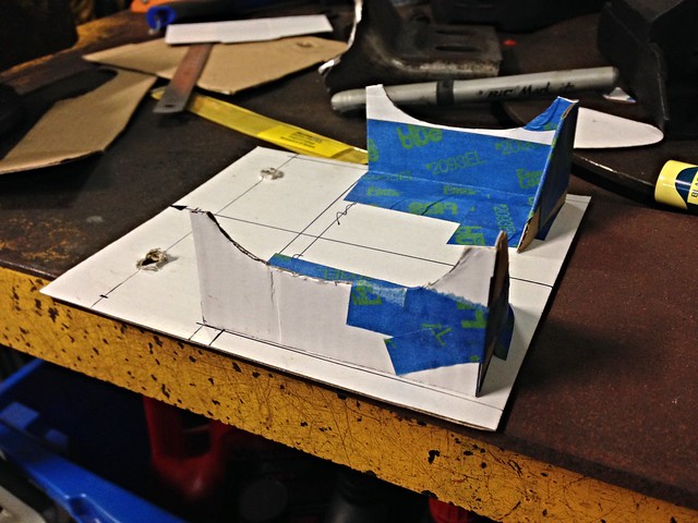
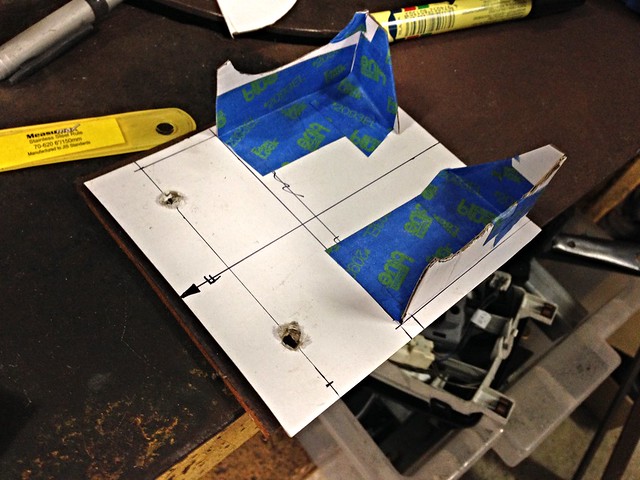
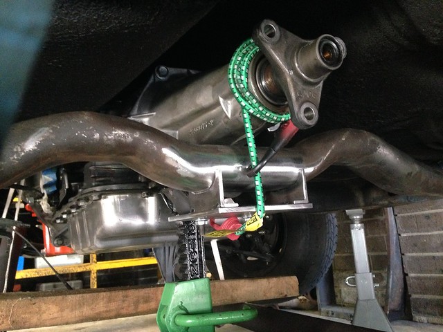
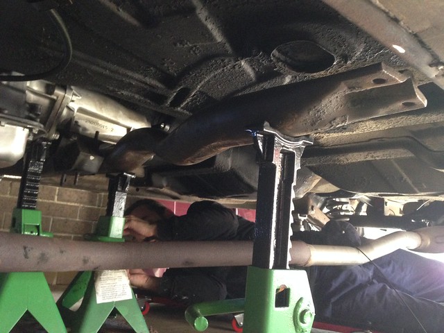
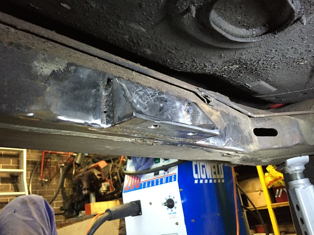
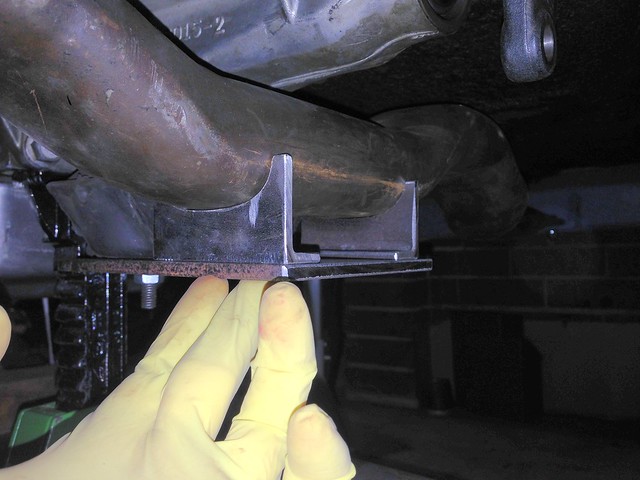
I soon discovered (after the photos above) that the transmission mount studs are offset across the car... a couple of punches with a scribe and new holes in the correct location were added.
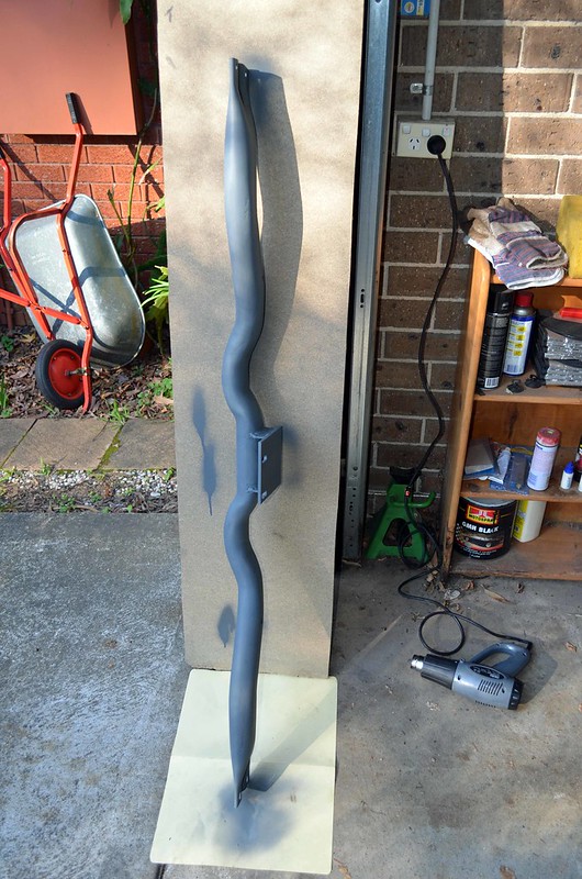
Cardboard was substituted for steel, with the template profiles traced onto 5 mm thick plate for the base and UA 40 x 20 for the uprights.
Then it was cut, grind, test-fit, rinse and repeat.
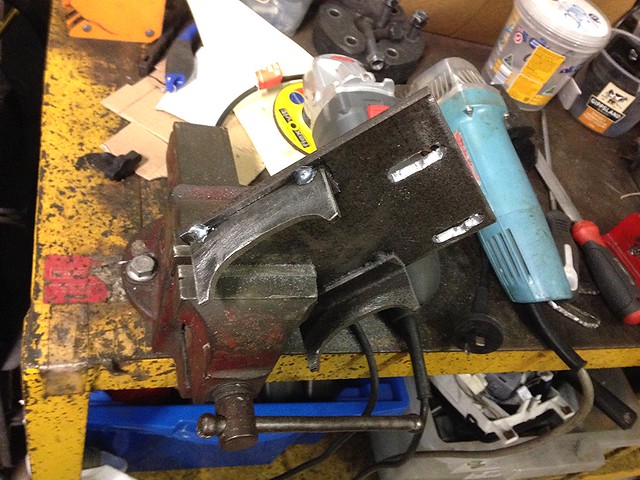
The curves in the uprights were offset by a few mm, spotted with a punch ever 5 mm or so and drilled out like Swiss cheese to the point were vice clamps could bend the scrap off, leaving behind a rough curve to be smoothed out by grinder/file.
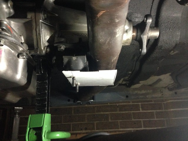
Test fitting the curved sections:
Not quite there...
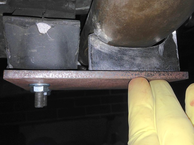
Much better...
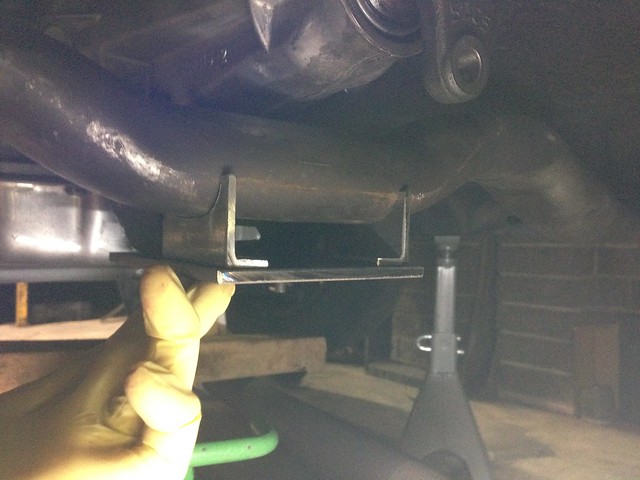
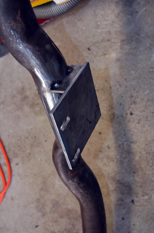
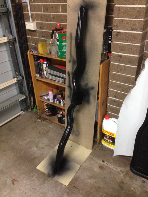
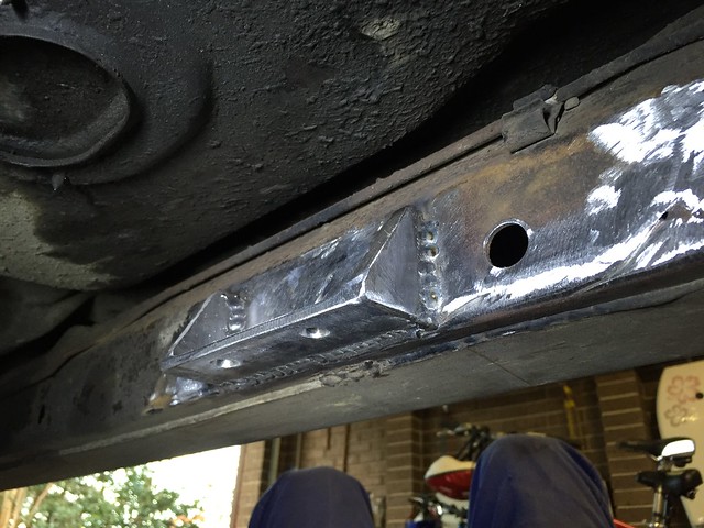
Each upright was vice clamped to the base in its final position and brought out from under the car for tacking on the bench.
Result (note the offset mount holes)...
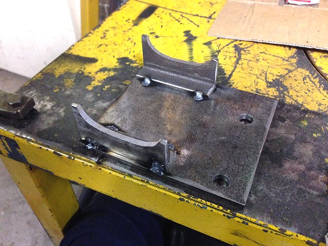
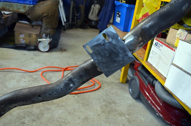
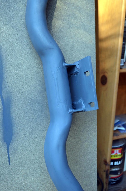
Finally, the mount holes were slotted to allow the cross member to be removed from the car without the holes fouling the studs...
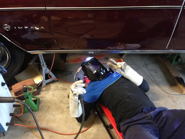
Next: tack the mount into position onto the cross member.
J