This all means a test frame needed to be made up to mount it all.
The design is a simple rectangular base using Dexion-style racking sections:
- Long pieces were cut-down to the required length with the angle brackets salvaged and welded back on at the cut end. Cross pieces at each end and the centre.
- 5PL feet on the end brackets for the 125 mm dia. castors (c/w lock-down brakes) to bolt to.
- Along each long-side of the base, JtC stitch-welded short lengths of C-section at the location of the engine and the gearbox. This would allow us to adjust the positions of the engine and gearbox cross-members, before clamping them into position.
- The gearbox uprights were C-rail sections with 100 x 50 x 5PL feet welded at each end. The feet allowed you to clamp-down on the base once the longitudinal position was reached.
- Gearbox cross-member was UA 40 x 20 with 100 x 50 x 5PL welded at each end. The plated ends were clamped to the upright C-sections once the correct height was reached.
- The engine cross member was heavier C-section to take the weight of the engine. Again, 5PL feet were welded to the ends to allow adjustment in the longitudinal direction, before clamping down.
- The engine mount uprights had feet at both ends, bottom feet to pick-up the cross member C-section and top for the standard LS2 engine mounts to bolt to.
A simple that allow adjustment to suit a variety of engine/gearbox combinations. JtC's welding skills well and truly came to the fore!
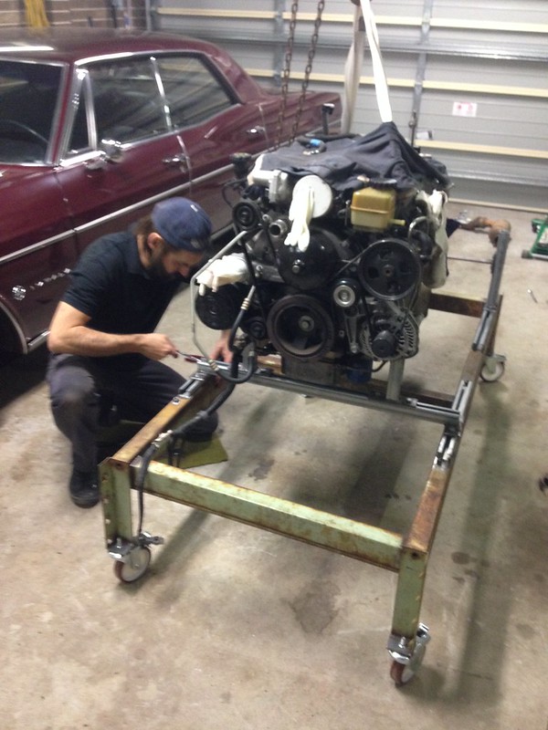
With the base frame welded up, castors on and the engine/gearbox mounts in place, it was time to lift... action shot!
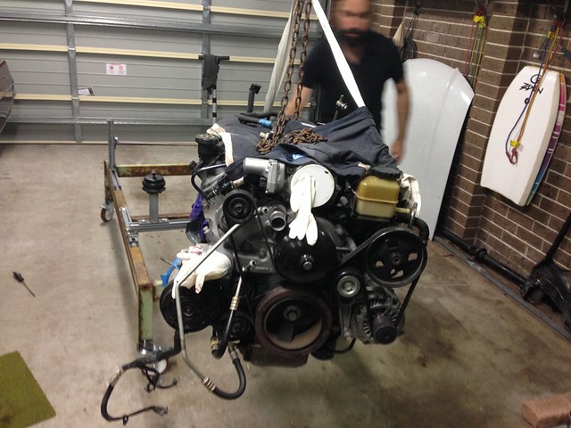
Bolting-up...
Like a bought one!

With the L76 + 4L65E bolting in place, it is time to plumb the cooling circuit + fuel + electrics... stay tuned!
J
No comments:
Post a Comment