Saturday, 27 August 2016

More fuelling around...

During the week, more bits turned up...

New Parts

More tank liner material, as well as some other bits that are for a later post.

JtC made the trip north to see what damage I had caused with the tank install.

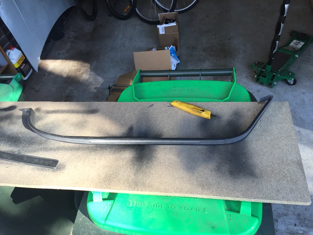
First task: clad the tank straps with rubber liner.

As is so often the case, reproduction parts don't quite fit and for us the new straps were a smidge too wide for the strap liners.

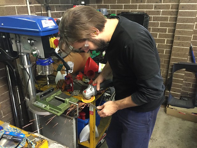
Angle grinder time...

Trimming the tank straps


Voila!

Tank Strap Lining


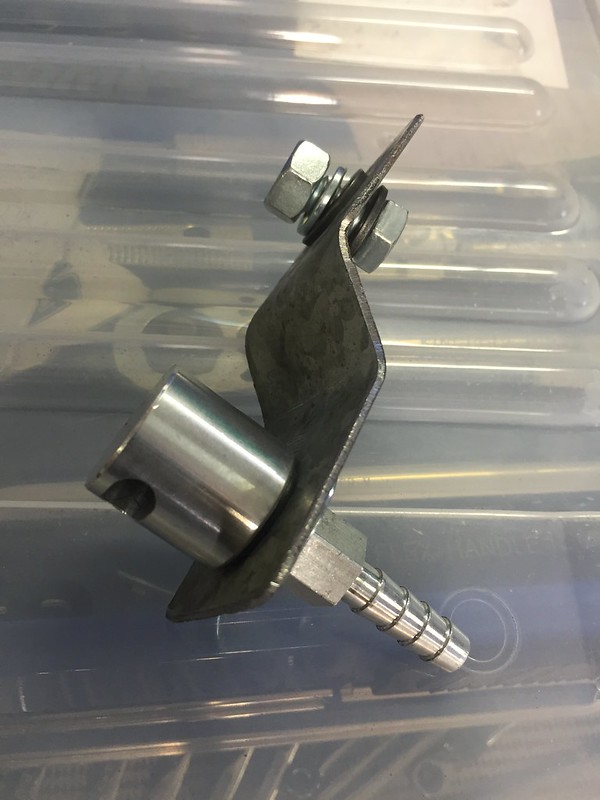
Next: mounting the tank vent/roll-over ball valve.

Bit of scrap gal steel bent into a z-bracket...

Tank Roll-over Valve/Breather Bracket


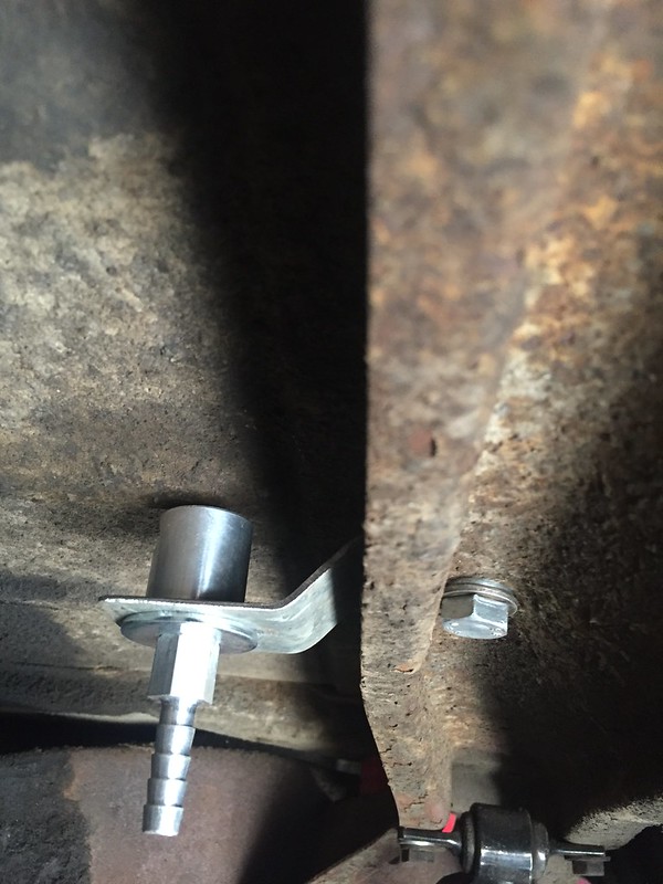
Bolted in place, on the brace that the rear shocks bolt to...

Tank Roll-over Valve/Breather Mounted


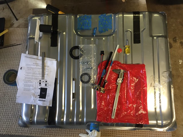
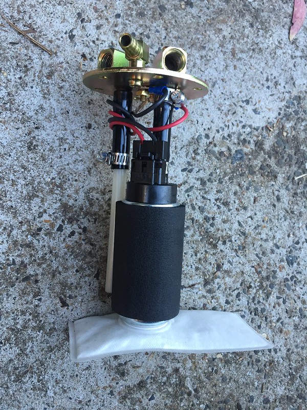
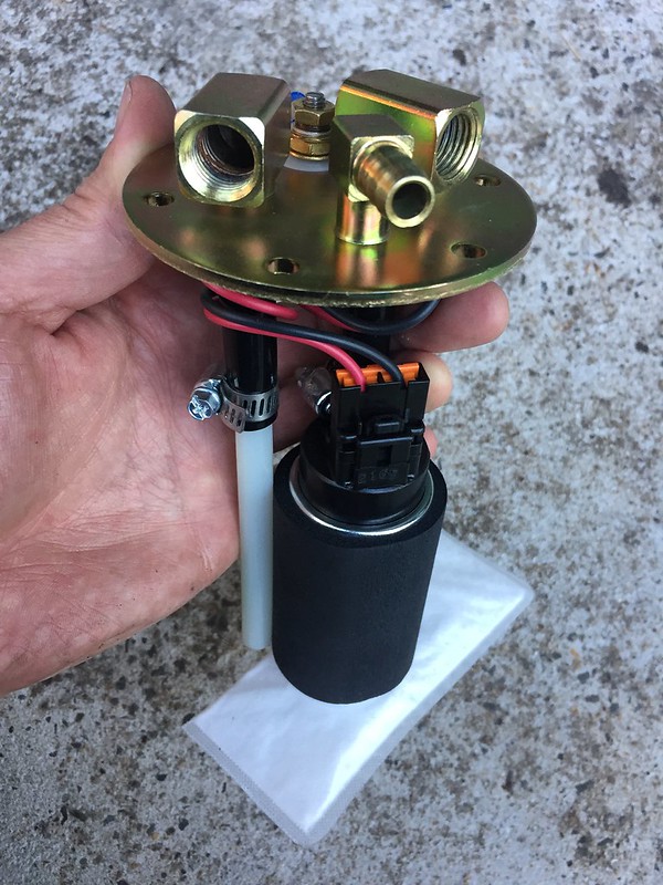
Finally: fitting the in-tank fuel pump and sender...

Measuring-up and Marking-out

Fuel Pump Assembly

Fuel Pump Assembly

J

Sunday, 14 August 2016

Tank Goodness

There are few options to go EFI in a '65 Impala...
1. Keep the existing fuel tank and feed the engine from an external fuel pump.
2. Keep the original tank and modify it to take an internal pump.
3. Purchase a new tank that mimics the original, but is modified to take an internal pump.

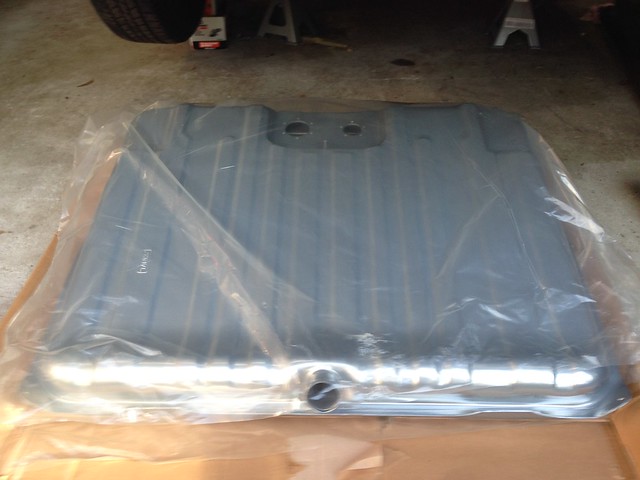
I went with option three, a new EFI-ready fuel tank from Tanks Inc, ordered through Summit....
Untitled

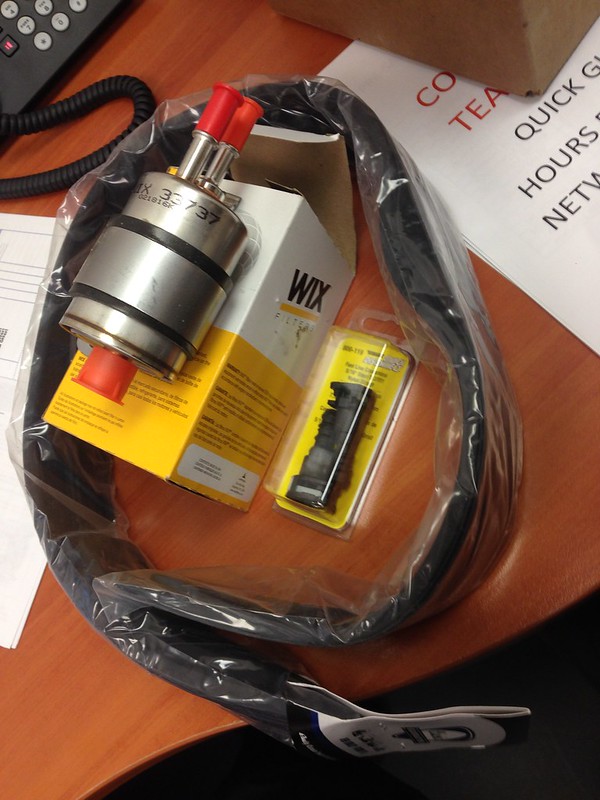
The way to go is to order an EFI tank conversion kit which comes with pump, sender and other required bits and pieces. There was a bit of a story (see here) around what was purchsed vs. what was supplied, but Summit came good and all is sweet!


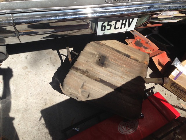
First: remove old tank.
Untitled


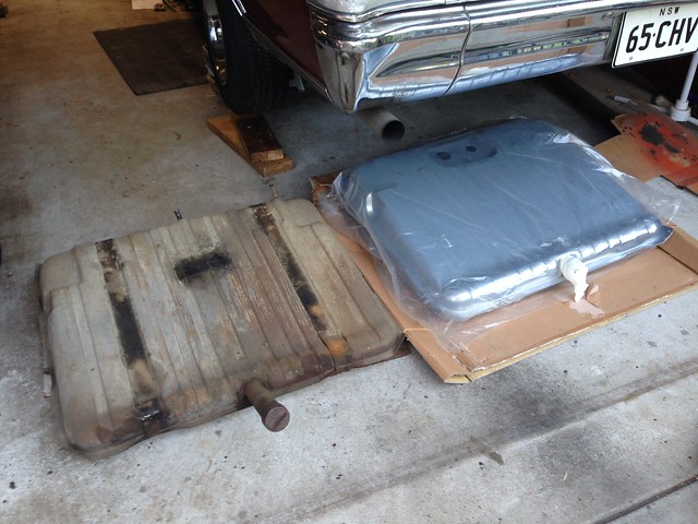
New and the old...

Untitled

The Tanks Inc product is (so far) excellent; beautiful powder coated finish, recessed area for mounting the pump/sender and baffled sump under the pick-up to reduce fuel starvation during corning/braking/accelerating.


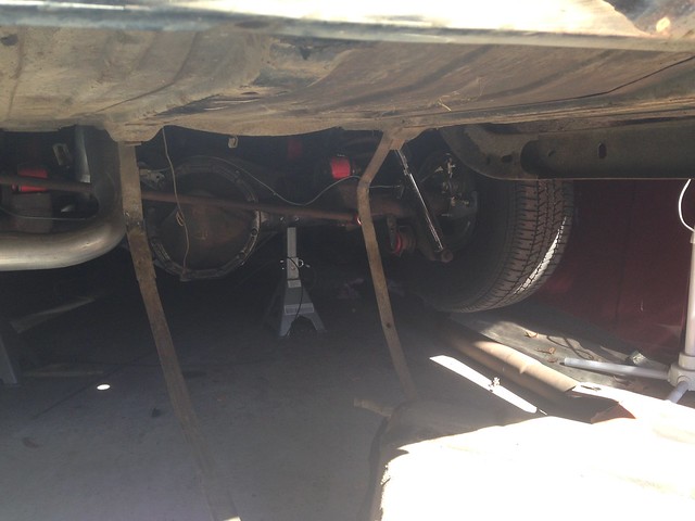
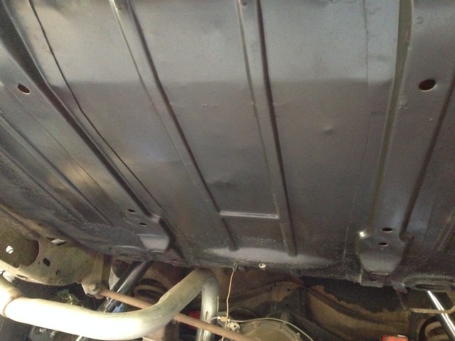
Second: A quick tidy-up of the underside of the boot floor.

Before...
Untitled


Wire wheel, wire wheel, wire wheel, prime, paint. After...
Untitled

Sooo much satin black on this car!

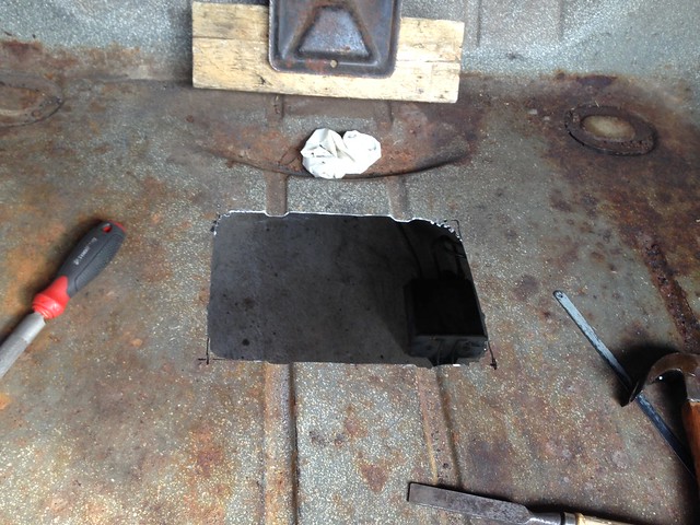
Third: butcher the boot floor pan...
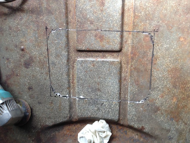
Untitled

Untitled


I contemplated not cutting the floor, but access to the fuel pump/sender will be sooo much easier with a hole. It is a pretty simple decision. Do. It...
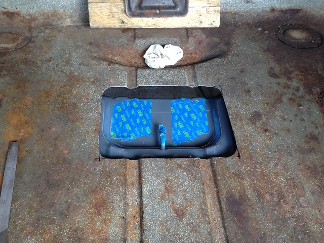
Untitled


Four: Fitment...

Untitled

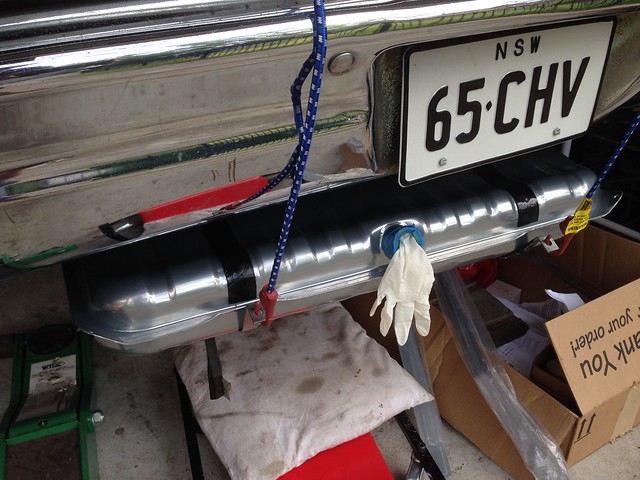
I also purchased tank lining material to avoid damaging the tank surface finish - you can see the black strips on the top of the tank - however there wasn't enough to line the straps as well so I ordered more rubber lining material and have left the tank hanging by occy straps until the rest of the rubber liner arrives.

J
Saturday, 30 July 2016

Transmission Linkage

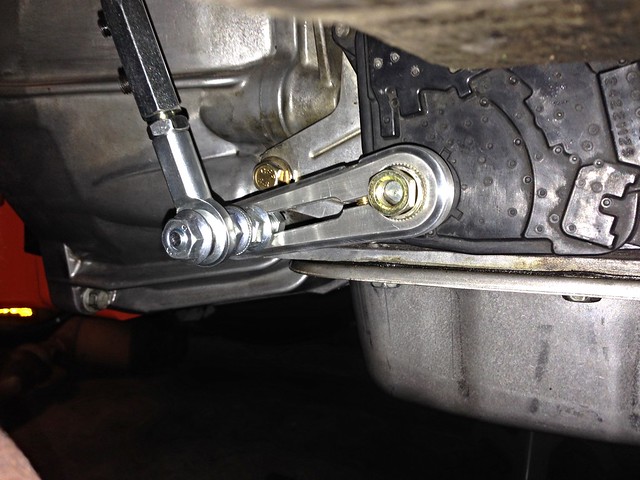
I want to keep the standard column shift, so picked up one of these:
Lokar Column Shift Linkage ACA-1800.

Nice bit o' kit!

Very adjustable, so it took a while to get right with JtC under the car making the adjustment while I shifted gears.

Installed...

Untitled


Don't be scared to put a bend in the link bar...


Initially we tried with the link rod straight from the column to the trans, but the angles were too severe for our liking. The arrangement in the above photo seems to work  treat.

J

Saturday, 23 July 2016

Park Brake Mods

So, on to mocking-up the refined handbrake design/layout...

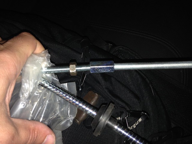
First, gathering the bits. The threaded rod from the pedal needs to be lengthened. We used 5/16" UNC threaded rod to match the existing, with a union and lock nuts on either side (only one shown here)...

5/16" UNC Union + Threaded Rod


A view of it assembled in the car - without lock nuts (this shot also highlights the need to shroud the threaded rod to keep in from abrading on the trans x-member)...

Mocked-up


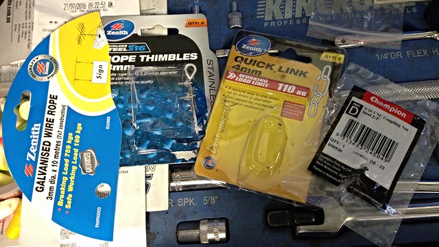
The rest of the bits...

Untitled


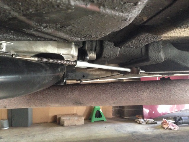
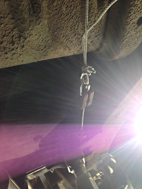
Was unable to find swaged ends for the intermediate cable, so resorted to screw links, clamps and thimbles (if requied, I'll get the final cable swaged at the right length).

Here I just have the one clamp in place to finalise the cable length. We have since ganged clamps together on both sides and trimmed the cable length to suit...

Untitled

J
Monday, 18 July 2016

Transmission Crossmember - Part 6 FINAL!

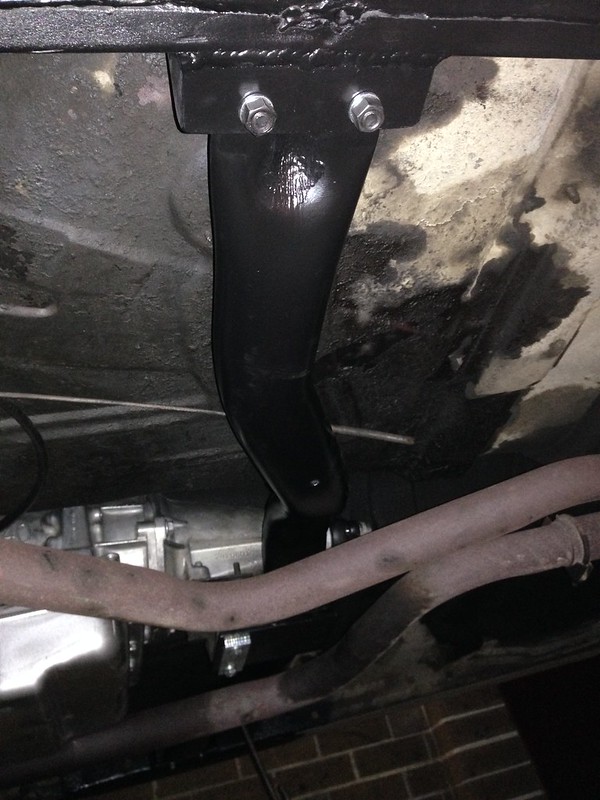
Aaaand bolted in place...

Untitled

Next: sorting the handbrake.

Now that we have moved the trans x-member towards the rear ~ 200 mm, all the geometry of the handbrake middle cable has changed as it hangs said cross-member.

J
Saturday, 25 June 2016

Transmission Crossmember - Part 5

With the bracket tacked together on the bench (in part four of our transmission cross-member mini-series) it was time to tack-weld the bracket to the cross member.

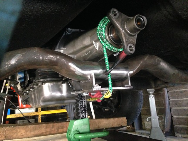
Bolted to the trans and held in place against the curved pipe of the cross-member with a trusty occy strap...

IMG_2823


A few spot welds and the bracket was located.

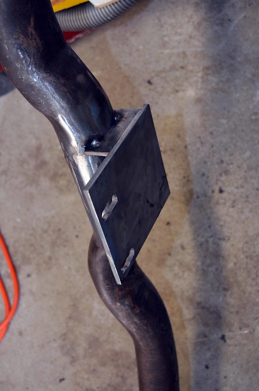
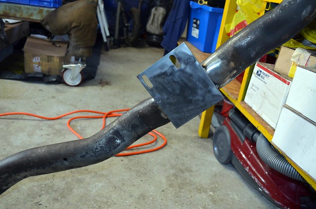
Removing the cross member - with the bracket attached - became problematic... much pushing and shoving and cutting-down the mounting studs didn't help. The go is to unbolt the mount from the trans and bingo! Job done.

Out of the car...

FabXmember03

FabXmember04


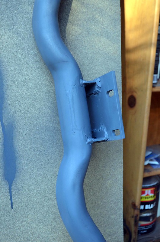
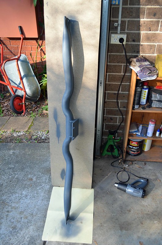
Welds were run (no fashion awards, but it ain't going anywhere) and hit with primer...

FabXmember06

FabXmember05


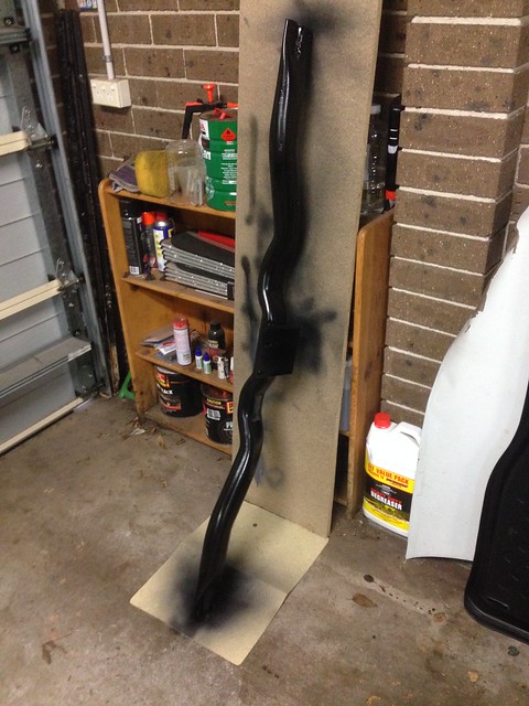
Then a couple of coats of satin black...

IMG_2828

J

Sunday, 19 June 2016

Transmission Crossmember - Part 4

More arts n' crafts this weekend as the mocking-up of the modified transmission cross member continues.

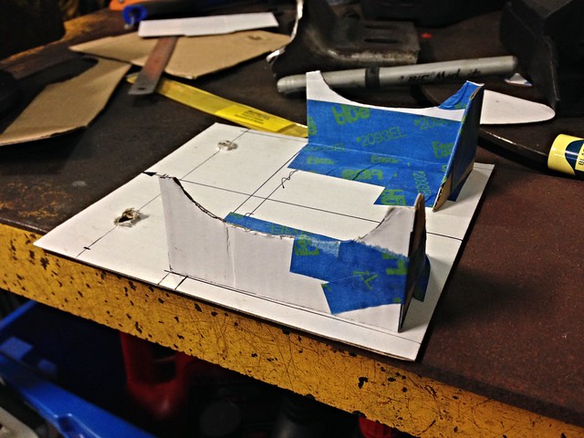
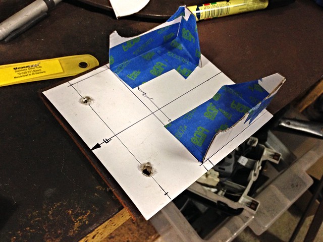
Template complete...

Template_01

Template_02


I soon discovered (after the photos above) that the transmission mount studs are offset across the car... a couple of punches with a scribe and new holes in the correct location were added.

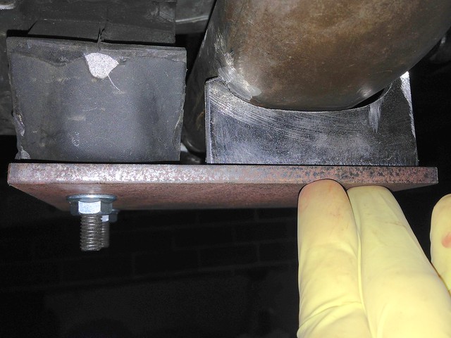
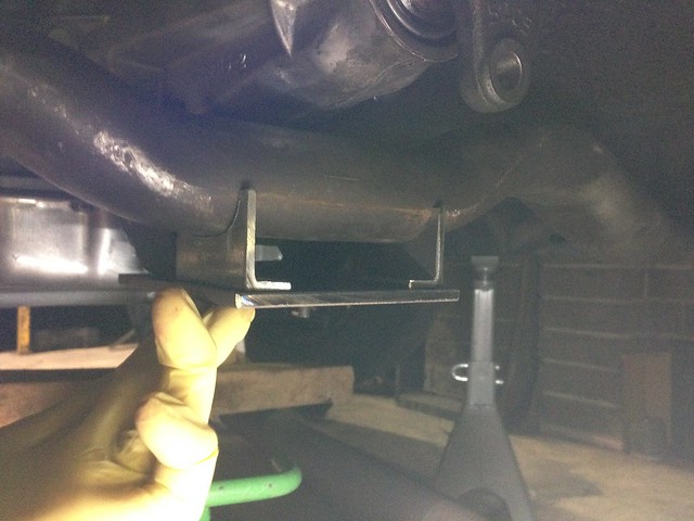
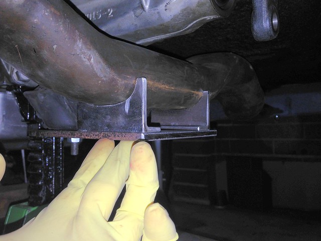
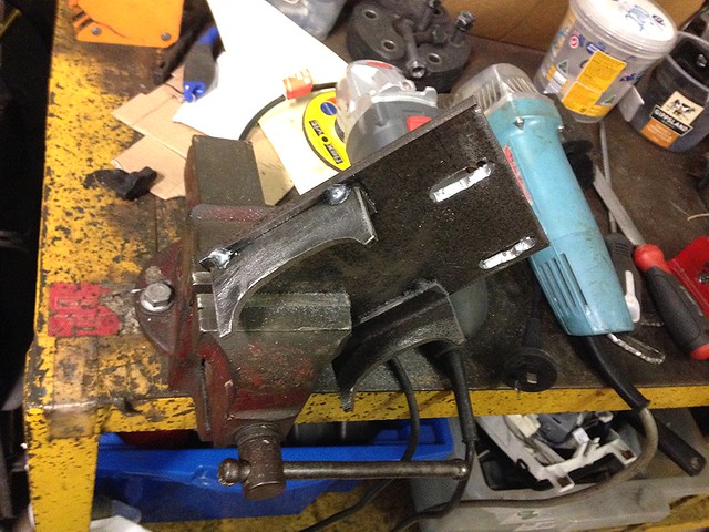
Cardboard was substituted for steel, with the template profiles traced onto 5 mm thick plate for the base and UA 40 x 20 for the uprights.

Then it was cut, grind, test-fit, rinse and repeat.

The curves in the uprights were offset by a few mm, spotted with a punch ever 5 mm or so and drilled out like Swiss cheese to the point were vice clamps could bend the scrap off, leaving behind a rough curve to be smoothed out by grinder/file.

Test fitting the curved sections:

Not quite there...

Dummy-up_01


Much better...

Dummy-up_03

Dummy-up_02


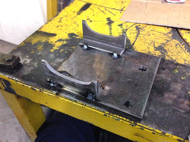
Each upright was vice clamped to the base in its final position and brought out from under the car for tacking on the bench.

Result (note the offset mount holes)...

Tacked


Finally, the mount holes were slotted to allow the cross member to be removed from the car without the holes fouling the studs...

Slotted


Next: tack the mount into position onto the cross member.

J

Saturday, 11 June 2016

Transmission Crossmember - Part 3

JtC headed North with the mission to weld new transmission cross member saddles to the chassis rails.

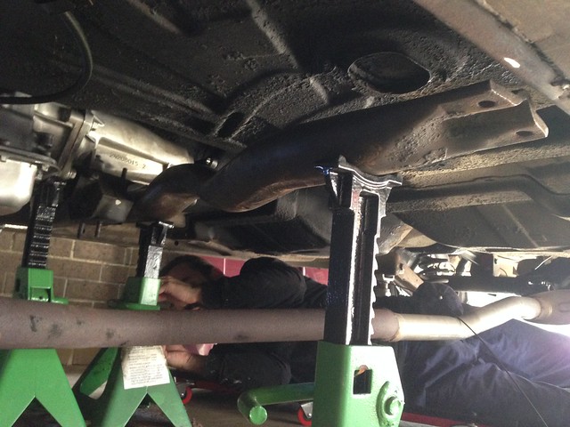
First: dummy-up where the cross member is to sit; axle stands everywhere...

Axle stands everywhere...


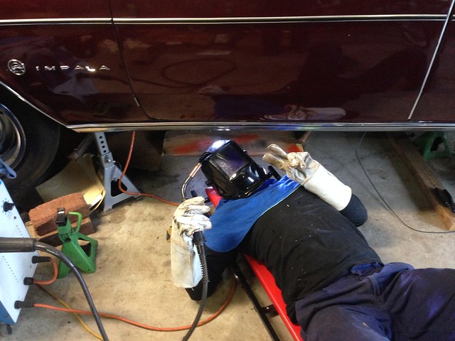
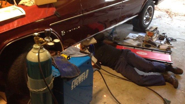
With the final location decided upon, the welding could start...

IMG_2790


IMG_2792


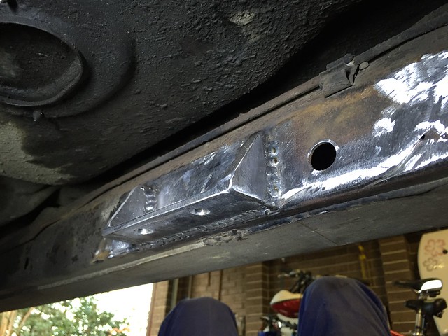
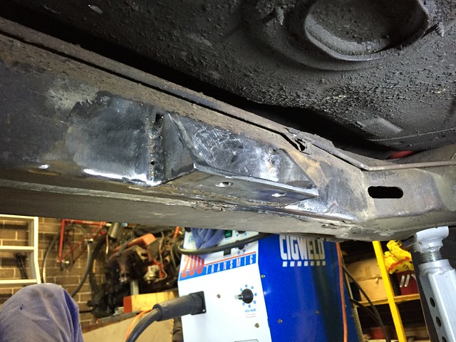
With nice clean shiny metal, more weld, bigger welds and thicker gauge steel than Chev ever used in the 60's, the result was very tidy indeed!

New Saddle

New Saddle


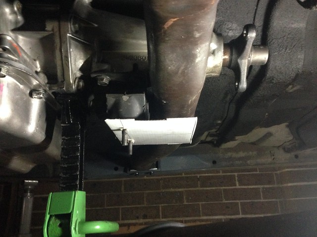
The cross member was soon bolted in place so the mocking-up of the mounting bracket could start in earnest...

Cardboard Template


More to follow...

J

Wednesday, 1 June 2016

Ancillary Drive Belt


1960 mm long, un-tensioned with the idler pulley in the "short belt" configuration.


Now need to subtract 28 mm as per Holley's instructions (extract below)...


However, a trial fit with the existing VZ Commodore belt has the tensioner wound all the way over to maximum tension and the belt juuuust fits on... where the belt length is 1995 mm (6PK1995).

Hmmm...

J

Monday, 30 May 2016

Ancillary Drive (the devil is in the details)

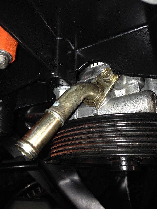
The VZ Commodore power steering pump had the inlet pipe pointing in the wrong dimension.

Originally the plan was to try and bend/twist the inlet pipe but too hard in the end.

Plan-B: source a new inlet pipe.

The KYB make of power steering pumps have an inlet that pushes into an o-ring and is held in place by a keeper plate. From various photos throughout the web, it looked like KYB standardised on the pipe diameter/keeper plate arrangement and simply changed the direction the pipe was bent to suit the vehicle it was going into.

After a bit of a dig through photos and visiting the wrecker near work with a set of verniers, I went for a second hand Hyundai unit from eBay.

The inlet pipe was duly unbolted and - thanks goodness - has an identical mounting arrangement to the Commodore's!

It was soon bolted to the Commodore pump and dummy-fitted to the ancillary drive bracket...

Hyundai Pump 03


So the orientation of the inlet is MUCH better. You can see in the photo that the relief in the bracket sits hard against the keeper plate bolt. The angle grinder came out and five millimeters was quickly removed.

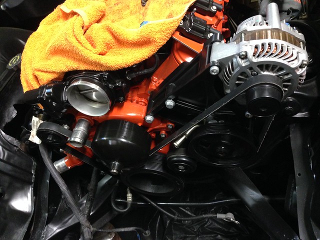
Went ahead and bolted the alternator, idler pulley and tensioner into place. Juuust managed to get the Commodore drive belt on (need to get a longer one) with the tensioner at the extremity of its travel...

Hyundai Pump 04

Evident in the photo above, the power steering pump inlet peeks out between the belt and the power steering pump pulley.

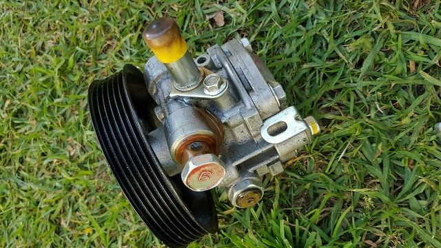
It is all a bit tight for my liking so time for Plan-C, enter one Mitsubishi Lancer power steering pump...

Lancer_PS_01

Here the inlet is vertical into the pump, so no belt clearance issues (I hope!).

I pick it up next week, stay tuned.

J