Showing posts with label electrics. Show all posts

Sunday, 26 February 2017

Speedo Controller

The desire has always been to keep the exterior and interior as stock as possible.

For the interior, rather than go for a dash with electronic displays driven by the ECU, the plan is to keep the original dashboard and have the speedo driven by an aftermarket controller that gets its input from the VSS, controls the speed of a stepper motor which drives a traditional mechanical speedo cable.

Enter the Dakota Digital Electric Cable Drive Speedo Control Unit (ECD-100-1) purchased through Summit.


Controller unit mounted in the glovebox...

IMG_3655


IGNORE! WRONG! BAD! The red wire in the photo here is (incorrectly) wired to battery positive, it has since been (correctly) wired to switched positive (ignition-on)...

IMG_3660


Calibrating button (switch). Still need to be mounted out of site, but this will do for calibrating...

IMG_3657


ECD-100-1 manual.

The whole setup works a treat and is easy to calibrate... highly recommended!

J

Friday, 2 December 2016

Swappin' Relays + Grit Blasting

---------- Forwarded message ----------
From: John
Date: Fri, Dec 2, 2016 at 12:56 PM
Subject: Verrry interesting...
To: JtC

Yo!

This morning I swapped the fuel pump relay with one of the thermo fan relays and gave it a start. Buzzing as usual. I thought I would check fault codes...


P0036
P0056
P0463 and
P0483
...are all usual suspects, no problems there.

The interesting one is P0480...
Cooling Fan Relay 1 Control Circuit

Extract:
"The causes for this DTC may include:
  - Faulty fan control relay 1"

Don't know B2aaa, but I think "B" is something to do with body control module (which is deleted). I know the low-speed thermo fan function is managed by the BCM, so there is every chance it is tied-in with P0480.

Video here...

After switching the car off I swapped the relays back again.

A few other things...

Coolant is below the top of the core.

Packed the bonnet hinges and bonnet latch into the Commodore in the hope that I can find some time this arvo to give them a grit blast.

< Edit... done! Photo below >


With all the starts I have been giving the Chev this week, I decided to disconnect the negative terminal and put the battery on trickle charge.

J

Saturday, 7 November 2015

Wiring

A nice aspect of the test frame being 100% steel is the ability to earth back through the frame as if it were a car body; plus the C-rails meant there were locations to easily connect/disconnect earth straps...

Wiring009


We - thankfully - kept the battery terminals/cables off the VZ, which were pressed back into service...

Wiring008

Wiring012


Wiring the ignition switch and testing...

Ignition Switch Wiring Test


Red = power from the battery
Brown/white stripe = accessories
Orange = ignition on
Purple = starter

Ignition Switch Wire Colours

J

Thursday, 5 November 2015

Fans are go!


Red = positive 1st fan
Green positive = 2nd fan
Black = common negative
Not sure about yellow... low speed?

Wiring003


I've come to be a BIG fan (pardon the pun) of terminal strips! Perfect for temporarily wiring-up on the test frame.

J

Fuel pump sorted

Put 12V across it and it whirred away happily.

Purple/white = power
Black/white = earth


Normally it would be...
Solid purple = power
Solid black = earth

Because the VZ was a ute, it had a separate fuel pump control module to reduce the fuel pump speed (and therefore noise) under low demand as the pump is close to the cabin.

The white-striped wires connected the fuel pump to the fuel pump control module, with solid purple/solid black wired into the module from the harness on the computer side.

Make sense?

J

Sunday, 9 October 2011

Electrics #2

Joe is back today to continue part 2 of the electrics saga. Today's installment... the rear of the car, namely reverse lights and number plate light.

The Chev came with a blown reverse light fuse. Replacement of said fuse and re-testing simply blew the fuse again, so there is a short.

Breaking out the test light and tracing the wires back from the reverse switch showed we had power all the way to the back of the car.

Once at the back, we could tell the car had been in a minor bingle in a previous life as the LHR brake light bulb sockets were non-original (and badly fitting, incorrect replacements!) c/w splices in the wiring.

It wasn't long before the trouble shooting super powers of JtC came to the fore when we found a short in the RHR indicator bulb socket...
ImpalaElectrical04

The good one (LHR) is shown here, but the photo shows the live centre contact (live) that was bent in the dodgy one and was touching the bulb socket (earth) itself - which was depressed into the plastic housing - and, hence, creating a short.

After removing this short - and a quick test - we (thankfully) found that this was the only short. Nice!

So the decision was to run up to Auto One and see if we could source some generic replacement bulb sockets that would fit for both the dodgy LHR stop lights and both rear indicators.

A quick search found these:
Narva 49828 (Single Contact Bulb Housing)
Narva 49838 (Double Contact Bulb Housing)

Both were a perfect fit for the indicator and tail lights respectively. A HUGE win! We grabbed some spare stop light bulbs, spare indicator bulbs and spare fuses.

We also grabbed a replacement number plate bulb as a quick test at home showed it was only a replacement bulb that was needed. Simple fix.

Once home, soldering ensued...
ImpalaElectrical08


Finally a picture (or two) tells a thousand words...

ImpalaElectrical06

ImpalaElectrical05

A HUGE day in the hunt for a Blue Slip! not much left on the list now.

Friday, 7 October 2011

Electrics #1

JtC is back! And I had the day off as annual leave, so it was a perfect day to Chev.

With the Chev on stands, it would make an awful noise if dropped into drive. JtC suggested it was tailshaft brushing the exhaust with the rear axle and gosh darn wasn't he 100% right... phew! I had images running through my head of some exy repair.

Next, idle mixture adjustment...

IdleMix01


Both idle mixture needles were 1.5 turns out of the seated position, so Joe set them both to 2 turn out to give a slightly higher idle speed.

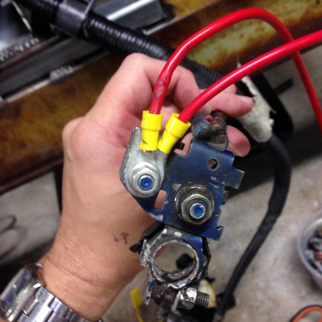
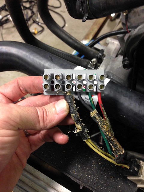
Then it was electrical time. First project, LHF indicator.

The test lamp showed no power at the bulb, so we traced the prob back to (most likely) the indicator switch... and that meant steering wheel removal.

Banging and pulling with hands didn't do anything so we had fabricate our own Driver-patented* steering wheel puller...

SteeringWheel02

SteeringWheel01

A few twists of the socket and voila! Steering wheel off.

Digging into the bowels of the steering column soon revealed the indicator switch where we discovered a weird arrangement where a plastic spigot would push a strip of metal onto another to make contact... ok, so not so weird. The weird part was the strip would make contact and complete the rear indicator circuit first, then continue its travel and make further contact to complete the front indicator circuit. Weird.

It was at this point we found the strip could not quite travel enough to make the second contact (i.e. active the front indicator circuit) on the LH side.

IndicatorSwitch02


A quick adjustment with needle nose pliers...

IndicatorSwitch01


...and double voila! We had the LHF indicator!

We noticed the outer component of the indicator switch had a crack through it, so time to source a new one and replace it before we return the steering wheel to its rightful home.


*may or may not be patented.