Holden Commodore VZ Series II SS-V Thunder ute delivered (received 08.08.2015).Engine (L76) and gearbox (4L65E) removed from ute (completed 16.08.2015).Source the engine mount adapter plates (received 04.09.2015).Drop harness + ECU to harness mod guy + discuss requirements (delivered 01.09.2015).Source steel for the test stand (picked-up 03.09.2015).Finish drawing the engine + gearbox test stand in CAD (completed 04.09.2015).Remove VZ fuel tank, fuel lines, etc... gut the ute (completed 06.09.2015).Source exhaust headers (picked-up 07.09.2015).Source the LS3 dipstick + dipstick tube + dipstick tube O-ring (received 15.09.2015).Source a Fel Pro oil pan gasket(received 16.09.2015).Source a radiator + electric cooling fans (picked-up Thu 01.10.2015).Pick-up modified harness + unlocked computer (picked-up Thu 01.10.2015).Source castor wheels for the test stand(received 06.10.2015).Weld-up the test rig and fit castors (final piece picked-up on Mon 19.10.2015).Get rid of the VZ shell on eBay (picked-up on 22.10.2015).Fit engine + gearbox on test stand (complete Fri 23.10.2015).Source radiator hoses to-suit (picked-up Wed 28.10.2015).Source a VE V8 MAF sensor (picked-up Thu 29.10.2015).Bypass ATF cooler (completed Thu 29.10.2015).Plumb the radiator + radiator hoses onto the engine/test stand (completed Thu 29.10.2015).Bypass the steering rack (power steering circuit) (completed Fri 30.10.2015).Plumb the coolant reservoir onto the engine/test stand (completed Fri 30.10.2015).Source 2 x pre-cat oxygen sensors (picked-up Fri 30.10.2015).Fit headers + O2 sensors onto the engine (completed Fri 30.10.2015).Plumb VZ fuel tank + lines + filter onto the engine/test stand (completed Fri 30.10.2015).Source a battery/starter pack (borrowed JtC's Fri 30.10.2015).Plug-in the modified harness to all engine + gearbox sensors (completed Fri 30.10.2015).Thread repair on right bank exhaust manifold bolt hole (completed Mon 02.11.2015).Wire up the fuel pump + starter + fans + ignition + battery (completed Sun 08.11.2015).Source a Wi-Fi OBD2 adaptor for diagnostics (completed Sun 08.11.2015).Source OBD2 scanning software for the laptop/iPhone (completed Sun 08.11.2015).Source fluids + filters and fill all reservoirs (completed Sun 08.11.2015).TEST RUN #1: check the ECU and harness works (completed Sun 08.11.2015).Finalise the OBD2 adaptor and software.Source new front and rear crankshaft seals (ordered 18.11.2015, received 20.11.2015).Source an EFI fuel tank to suit the Impala (ordered 12.11.2015, received 24.11.2015).Source a transmission shift adapter (ordered 12.11.2015, received 24.11.2015).Pull the L76 off the 4L65E (completed Sat 05.11.2015).Fit a new rear crankshaft seal (rear main seal) onto the L76 (completed Sat 05.11.2015).Fit the Holley oil pan onto the L76 (completed Sat 05.11.2015).Fit the LS3 dipstick onto the L76 (completed Sat 05.11.2015).Remove air con compressor (completed Sat 05.11.2015).Remove alternator (completed Sat 05.11.2015).Remove power steering pump + water pump + sensors (completed Sun 20.12.2015).Degrease and clean the L76 (completed Sun 20.12.2015).Paint the L76 Chevrolet orange (completed Sun 20.12.2015).Fit engine mount adaptor plates (completed Sun 20.12.2015).Degrease and clean the 4L65E (completed Tue 22.12.2015).Paint the 4L65E with clear coat (completed Tue 22.12.2015).Reattach the 4L65E to the L76 (completed Tue 22.12.2015).Paint inlet manifold + coils satin black (completed Thu 31.12.2015).Measure existing tail-shaft length (completed Thu 31.12.2015).Remove the 327 + Powerglide from the Chev (completed Sat 16.01.2016).Strip + clean engine bay (completed 06.02.2016).Paint engine bay with etch primer (complete 07.02.2016).Paint engine bay with satin black enamel - first coat (complete 10.02.2016).Paint engine bay with satin black enamel - final coat (complete 13.02.2016).Paint engine bay with clear coat (complete 17.02.2016).Clean and fit the alternator, PS pump and tensioner to the LS (complete 21.02.2016).Source new oil pressure light sender/switch (complete 24.02.2016).Source transmission breather T-piece (received 25.02.2016).Re-coat engine bay with satin black (complete 26.02.2016).Fit auto transmission cooling pipes (complete 27.02.2016).Source oil sender T-piece adapter (purchased 24.02.2016, received 07.03.2016).L76 + 4L65E into the Chev. Test-fit #1: (complete 29.03.2016)verify if the engine mount adapters locate the engine correctly (10 mm packers required).verify a new ancillary drive is required (alternator fouls X-member).verify the transmission fits (close, hammer-out tunnel near servo).verify the location of the gearbox cross member (looks close at first sighting).verify if the headers fit (close, move engine rearward).verify the driver-side coil packs clear the master cylinder (clear!).Remove the L76 + 4L65E from the Chev (complete 29.03.2016).Hammer-out transmission tunnel to clear the servo (complete 30.03.2016).Source a new ancillary drive for the L76 to suit the Impala (received 04.04.2016).Move engine mounts rearward by 33 mm (complete 21.04.2016).Manufacture new (taller) engine mount pedestals (complete 23.04.2016).Paint the new pedestals + ancillary drive brackets satin black (complete 24.04.2016).L76 + 4L65E into the Chev. Fitting #2 (complete 30.04.2016):Verify if the engine mounts + new pedestals locate the engine correctly (done!).Verify the transmission fits (done!).Verify if the headers fit (done!).Verify the location of the gearbox cross member (complete 15.05.2016).Cut-off the existing transmission cross member chassis rail saddles (complete 21.05.2016).Source a new PS pump inlet pipe to clear the ancillary drive bracket (received 25.05.2016).Fit the new PS pump inlet pipe (complete 25.05.2016).Manufacture new transmission cross member chassis rail saddles (complete 25.05.2016).Modify the ancillary drive bracket to clear the new PS pump inlet pipe (complete 26.05.2016).Bolt the power steering pump into place (complete 26.05.2016).Fit the rest of the new ancillary drive to the L76 (complete 29.05.2016).Source a new PS pump inlet pipe to clear the ancillary drive belt (picked-up 08.06.2016).Weld the new transmission cross member chassis rail saddles into place (complete 11.06.2016).Modify the transmission cross member (complete 25.06.2016).Bolt the transmission cross member in and mount the transmission (complete 18.07.2016).Mock-up the park brake arrangement (complete 18.07.2016).Source 5/16" UNC threaded rod + 5/16" UNC coupling nut + cable (completed 23.07.2016).Assemble park brake (completed 30.07.2016).Fit transmission linkage (complete 30.07.2016).Remove original fuel tank (complete 13.08.2016).Cut hole in boot/trunk floor for access to the in-tank fuel pump/sender (complete 14.08.2016).Dummy-up new fuel tank (complete 14.08.2016).Source a new (longer) ancillary drive belt. Ordered 2055 mm long (received 18.08.2016).Source new fuel tank hanger bolts (received 18.08.2016).Source fuel hose (received 19.08.2016).Source Corvette filter/regulator + plumbing hardware (received 25.08.2016).Fit EFI pump and sender to the tank (complete 27.08.2016).Source exhaust manifold gaskets (received 30.08.2016).Source a new ancillary drive belt. Ordered 2020 mm long (received 30.08.2016).Fit EFI fuel tank (complete 03.09.2016).Fit Corvette EFI fuel filter (complete 03.09.2016).Verify the location/length of all power steering lines (complete 12.09.2106).Plumb the supply/return fuel hoses between the pump and filter (complete 06.09.2016).Source AN fittings and hard line for the.fuel system(picked-up 15.09.2016)Source AN.fittings and hose for thepower steering system (picked-up 15.09.2016)Plumb the fuel hard lines from the filter to the engine (complete 18.09.2016).Plumb the fuel tank vent (complete 27.09.2016).Plumb the power steering system (complete 27.09.2016).Grit blast the headers (complete 28.09.2016).Verify the location of the radiator (complete 02.10.2016). Omit spacer.Dummy-up headers, verify if cats will be used (complete 02.10.2016). Yes, use cats!Cut engine pipes and tie the exhaust to the trans cross-member (complete 02.10.2016).Paint headers (complete 03.10.2016).Modify the radiator to bolt directly to the radiator support w/o spacer (complete 08.10.2016).Have the radiator modified for Commodore hoses (picked-up 12.10.2016).Source AN fittings for the.ATF cooling system(picked-up 15.10.2016)Fabricate thermo fan shroud (complete 15.10.2016).Fabricate thermo fan mounts (complete 15.10.2016).Mount the radiator (complete 16.10.2016).Fit electric thermo fan (complete 16.10.2016).Fabricate bottom coolant transfer pipe mounting brackets (complete 16.10.2016).Plumb the cooling system bottom hose assembly (complete 16.10.2016).Plumb the ATF cooling lines (complete 16.10.2016).Source a top radiator hose that suits (picked-up 21.10.2016).Plumb the cooling system top hose + trim fan shroud to suit (complete 22.10.2016).Measure required tailshaft length at full-droop & full compression (complete 22.10.2016).Verify the final length of the tailshaft (complete 22.10.2016)1,545mm (existing less 80 mm).Fit fuel tank filler neck (complete 22.10.2016).Mount the oil pressure sensor + adaptor + oil sender (complete 22.10.2016).Wire the oil pressure sender using the existing Chev wire (complete 22.10.2016).Ensure all sensors are bolted down before the headers go on (complete 22.10.2016).Source new exhaust header bolts (received 24.10.2016).Source steam pipe 10 mm to 6 mm hose reducer (received 27.10.2016).Source a new (shorter) tailshaft + new universal joints (picked-up 28.10.2016).Fit the new tailshaft (complete 30.10.2016).Fit new sparkplugs and leads (complete 30.10.2016).Fit headers (complete 30.10.2016).Fit the engine oil dipstick tube (complete 30.10.2016).Connect the gearbox wiring harness (complete 30.10.2016).Connect the engine-half of the wiring harness (complete 30.10.2016).Connect the heater hoses (complete 30.10.2016).Source intake bend + pipe + clamps + pod filter (picked-up 31.10.2016).Source top radiator hose clamps for 44 mm OD (picked-up 05.11.2016).Source fuel tank filler neck hose clamps for 62 mm OD (picked-up 05.11.2016).Fit top radiator hose clamps (complete 06.11.2016).Fit fuel tank filler neck hose clamps (complete 06.11.2016).Trim the radiator shroud to suit intake (complete 07.11.2016). No good! Need different fan.Open-up the clutch master hole in the firewall to ~ 3" dia (complete 07.11.2016).Line hole with split rubber hose (complete 07.11.2016).Feed the wiring loom through the firewall using the clutch master hole (complete 07.11.2016).Mount the transmission ECU (complete 07.11.2016).Source new exhaust flange gaskets (received 10.11.2016).Source Engine ECU + Trans ECU M6 anti-vibration mounts (received 14.11.2016).Source different profile radiator fan - Ford Falcon FG (picked-up 17.11.2016).Test thermo fan -> runs high speed only, low speed resistor burnt out (complete 17.11.2016).Source Dexron VI ATF (picked-up 18.11.2016).Source DEX-COOL Extended Life coolant (picked-up 18.11.2016).Source steam pipe 10 mm hose (picked-up 20.11.2016).Source steam pipe 6 mm hose (picked-up 20.11.2016).Fit thermo fan (complete 20.11.2016).Wire the fuel sender ground (complete 20.11.2016).Wire the fuel pump ground (complete 20.11.2016).Mount the intake pipe + MAF + pod filter (complete 20.11.2016).Plumb the cooling system steam pipe (complete 20.11.2016).Clean-up battery tray + paint (complete 20.11.2016).Fit battery tray + battery (complete 22.11.2016).Delete the existing Chev alternator wire (complete 22.11.2016).Hole through firewall for battery positive/thermo fan/starter wires (complete 22.11.2016).Source the starter trigger relay/base. Reuse existing VZ relay. (complete 24.11.2016).Source a plug for the thermo fan (complete 24.11.2016).Source a longer silicon reducer section (swap shorter section) (complete 24.11.2016).Source new battery cable/lugs/terminals (complete 25.11.2016).Create new battery/ground cables (complete 26.11.2016).Wire the battery positive/starter/alternator/ground harness (complete 26.11.2016).Wire the existing Chev battery positive harness (to horn relay) (complete 26.11.2016).Wire constant power source (red 2 x 6mm wires) (complete 26.11.2016).Wire the fuel pump (purple 4mm wire). Run wire under carpet PS (complete 26.11.2016).Wire the starter relay. Wire from Chev starter trigger + grey 2mm wire (complete 26.11.2016).Wire the thermo fan (green 2 x 5mm wires) (complete 26.11.2016).Temporarily hang the cats from the chassis (complete 26.11.2016).Wire the thermo fan ground (complete 27.11.2016).Wire ignition on (pink 4mm wire) (complete 27.11.2016).Wire into the brake circuit (red 2mm wire) (complete 27.11.2016).Wire the reverse lights (yellow 2mm wire) (complete 27.11.2016).Wire accelerator pedal (plug-in harness) (complete 27.11.2016).Add all fluids (complete 27.11.2016).Test run the engine (complete 27.11.2016).Test drive #1 (complete 27.11.2016).Source speedo control unit (received 29.11.2016).Swap buzzing fuel pump relay with neighbouring relay (complete 02.12.2016).Grit blast bonnet latch (complete 02.12.2016).Grit blast bonnet hinges (complete 02.12.2016).Paint bonnet latch (complete 03.12.2016).Paint bonnet hinges (complete 03.12.2016).Fit the bonnet latch (complete 04.12.2016).Fit the bonnet hinges (complete 04.12.2016).Fit bonnet (complete 04.12.2016).Mount the accelerator pedal (complete 04.12.2016).Test Drive #2 (complete 04.12.2016).Add body to engine earth strap (complete 06.12.2016).Remove existing headlight high beam dip switch (complete 06.12.2016).Source a headlight high beam dip switch (picked-up Wed 07.12.2016).Fit new headlight high beam dip switch (complete Wed 07.12.2016).New exhaust (complete Fri 09.12.2016).Mount the relay block (complete Sun 11.12.2016).Mount the fuse block (complete Sun 11.12.2016).New tyres (x 4) and wheel alignment (Mon 12.12.2016).Fix buzzing fuel pump relay (complete Thu 15.12.2016).Mount the engine ECU (complete Sun 15.01.2017). Temporary.Mount the OBD2 interface plug (complete Sun 15.01.2017).Mount the speedo control unit + connect speedo cable (complete Sat 18.02.2017).Wire the speedo control unit ground (complete Sat 25.02.2017).Wire the speedo control unit VSS feed (purple 2mm wire) (complete Sun 26.02.2017).Wire the speedo control unit calibration switch (complete Sun 26.02.2017).Calibrate the speedometer (complete Fri 31.03.2017).Engineer check and to-do list (pick-up Sat 15.04.2017).Swap rear indicators to flash the reverse lights (complete Sat 06.05.2017).Seal boot floor with velcro-attached lid over fuel pump hole (complete Sat 13.05.2017).Connect fuel vapour carbon canister (Sat 03.06.2017).Pod filter shroud (Sun 15.10.2017).Passenger side exterior rear view mirror (Sun 15.10.2017).New handbrake intermediate cable and assemble handbrake (Thu 26.10.2017).ADR compliant three point seat belts (Mon 20.11.2017).Reinstate original Chev brake booster (Sat 09.12.2017).Plumb crankcase ventilation into inlet (Sun 10.12.2017).1-1/8" bore master cylinder (Thu 28.12.2017).Source a hydraulic brake booster (arrived Fri 23.02.2018).Source AN fittings and hose for the hydraulic brake booster (Mon 26.02.2018).Fit hydraulic brake booster (Mon 26.02.2018).Engineering Certificate received (Wed 14.03.2018).Blue Slip received (Wed 14.03.2018).Signed club Classic Vehicle Scheme constitution sent. (Fri 16.03.2018).Club-stamped Classic Vehicle Declaration (1835) received (Sat 24.03.2018).ACMC-stamped Classic Vehicle Declaration (1835) received (Wed 28.03.2018).Conditional Rego - Classic Vehicle Scheme (CVS) for Modified Vehicles (Thu 29.03.2018).ECU Tune (pick-up Fri 11.05.2018).
Showing posts with label conversion. Show all posts
Showing posts with label conversion. Show all posts
Friday, 11 May 2018
LS Swap To-Do List
The priority of things:
Monday, 26 February 2018
Hydro-boost
Brakes always had a fair travel and needed a lot of force to haul the car up. The brake system couldn't lock the wheels and so the engineer wanted to see something better.
The disc brake conversion came with 1" bore master and 9" dia single diaphragm booster.
Swapped the booster for a dual diaphragm 8"... no dice.
Ended up going for a 1 1/8" bore master to reduce the stroke and a Hydro-boost brake booster to give the extra "oomph" required...

Made up high pressure hoses using Speedflow AN-6 fittings and Speedflow high pressure power steering hose...
Installed...

Wow! Chalk and cheese!
Standing on the brakes will lock all four tyres now. It has transformed the car and the engineer is well happy.
For anyone going to 4-wheel discs on an Amercian full-size, don't muck around with vacuum boosters... go with a Hydro-boost unit.
JRD
The disc brake conversion came with 1" bore master and 9" dia single diaphragm booster.
Swapped the booster for a dual diaphragm 8"... no dice.
Ended up going for a 1 1/8" bore master to reduce the stroke and a Hydro-boost brake booster to give the extra "oomph" required...
Made up high pressure hoses using Speedflow AN-6 fittings and Speedflow high pressure power steering hose...
Installed...
Wow! Chalk and cheese!
Standing on the brakes will lock all four tyres now. It has transformed the car and the engineer is well happy.
For anyone going to 4-wheel discs on an Amercian full-size, don't muck around with vacuum boosters... go with a Hydro-boost unit.
JRD
Sunday, 26 February 2017
Speedo Controller
The desire has always been to keep the exterior and interior as stock as possible.
For the interior, rather than go for a dash with electronic displays driven by the ECU, the plan is to keep the original dashboard and have the speedo driven by an aftermarket controller that gets its input from the VSS, controls the speed of a stepper motor which drives a traditional mechanical speedo cable.
Enter the Dakota Digital Electric Cable Drive Speedo Control Unit (ECD-100-1) purchased through Summit.
Controller unit mounted in the glovebox...
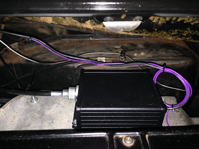
IGNORE! WRONG! BAD! The red wire in the photo here is (incorrectly) wired to battery positive, it has since been (correctly) wired to switched positive (ignition-on)...
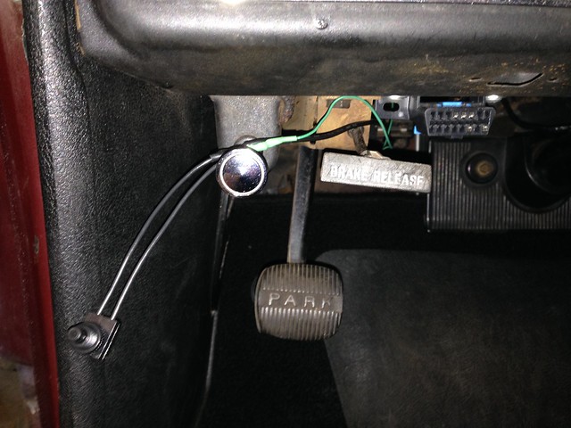
Calibrating button (switch). Still need to be mounted out of site, but this will do for calibrating...
ECD-100-1 manual.
The whole setup works a treat and is easy to calibrate... highly recommended!
J
For the interior, rather than go for a dash with electronic displays driven by the ECU, the plan is to keep the original dashboard and have the speedo driven by an aftermarket controller that gets its input from the VSS, controls the speed of a stepper motor which drives a traditional mechanical speedo cable.
Enter the Dakota Digital Electric Cable Drive Speedo Control Unit (ECD-100-1) purchased through Summit.
Controller unit mounted in the glovebox...
IGNORE! WRONG! BAD! The red wire in the photo here is (incorrectly) wired to battery positive, it has since been (correctly) wired to switched positive (ignition-on)...
Calibrating button (switch). Still need to be mounted out of site, but this will do for calibrating...
ECD-100-1 manual.
The whole setup works a treat and is easy to calibrate... highly recommended!
J
Sunday, 27 November 2016
The Big Push - Day 2 (wiring + fluids + START!)
Yesterday's efforts broke the back of the last leg to start-up, with the only remaining wiring being the interface with the existing Chev circuits:
- wire ignition on (pink 4mm wire).
- wire into the brake circuit (red 2mm wire).
- wire the reverse lights (yellow 2mm wire).
Then it was a case of adding all fluids, holding our collective breath and turning the key!
Nothing.
With "ignition on", we could hear the fuel pump relay click and the fuel pump whirr into life for a couple of seconds then stop. All good. Part of the design.
Then twist to start, we could hear the starter relay click, as well as a loud clack from the starter solenoid... but nothing.
After a couple of twists with nothing, one last twist caught and the engine stumbled into life...
A couple of things... you can hear some lifter tap, so there was a bit of concern around oil pressure. The idle is rough and hunting, plus the accel pedal did nothing.
We killed it and scratched our heads for a while; we needed to know what was going on.
I took a drive to a mate's house (Stu the Aussie champion) who lent me his OBD2 ELM327 adaptor. But on my return, JtC had nailed it!
The plug to the throttle butterfly was loose. A quick click and voila! Smooth idle!
We even had gears. First time in daylight for nine months...
A quick run up the hill showed that the thing was gutless as anything. Full throttle saw the car crawl up the hill... something awry there.
And one final issue, a buzzing from the relay that feeds the fuel pump...
One final video that highlights the baulk on start. The first crank is a no-go and the second fires...
So the issues are:
- baulks intermittently on start-up
- buzzing fuel pump relay
- gutless
Interestingly in the last video, the fuel pump relay is much quieter.
Time to do some research but the issues do not seem insurmountable.
HUGE thanks to JtC for all his efforts! There is no way I could have achieved all this in the time we did without his time, efforts and experience. Well done!
J
Saturday, 26 November 2016
The Big Push - Day 1 (wiring)
It has come to this.
Through the week I booked the exhaust for 9/12 and rego inspection for 12/12, so there is a real urgency now to knock-off the last items on the to-do list... the majority being related to keeping smoke within wires.
We had mini working bee Tue night to fit the battery tray and drill through the firewall on the passenger side for battery positive, thermo fan and starter wires.
During the week, various parts were acquired ready for a committed weekend of wiring...
- 25 mm2 cable (battery to starter, batter to alt, ground)
- lugs for 25mm2 cable
- distribution post for feeding battery +ive to various circuits
- relay base (will reuse a relay from the VZ for P/N start conditioning)
- plug for thermo fan connection
- 10mm dia split conduit
- 16mm dia split conduit
So to the weekend: a HUGE double header from JtC, making the trip north on both Sat (wiring till midnight) and Sun in an attempt to get the beast started.
First mission:
- Create new battery/ground cables.
- Wire the battery positive/starter/alternator/ground harness.
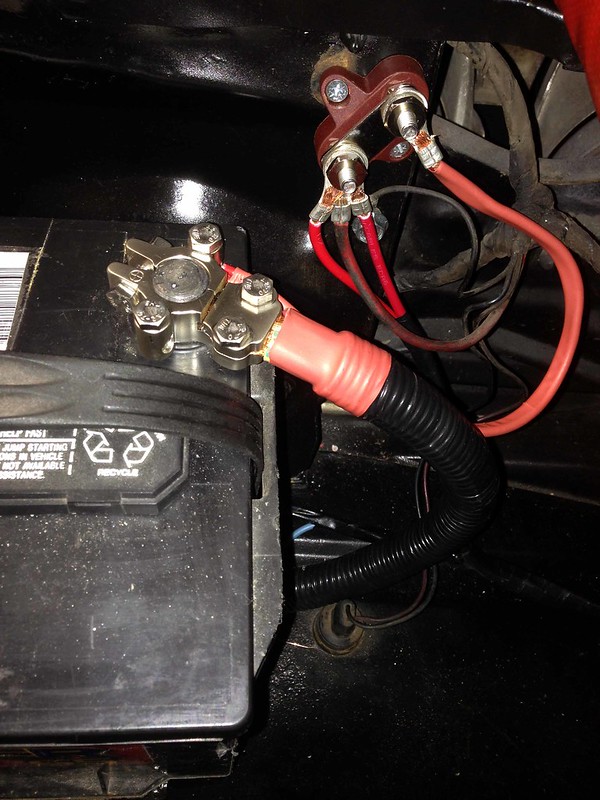
- Wire the existing Chev battery positive harness to the existing horn relay.
- Wire constant power source (red 2 x 6mm wires) from EFI to battery positive...
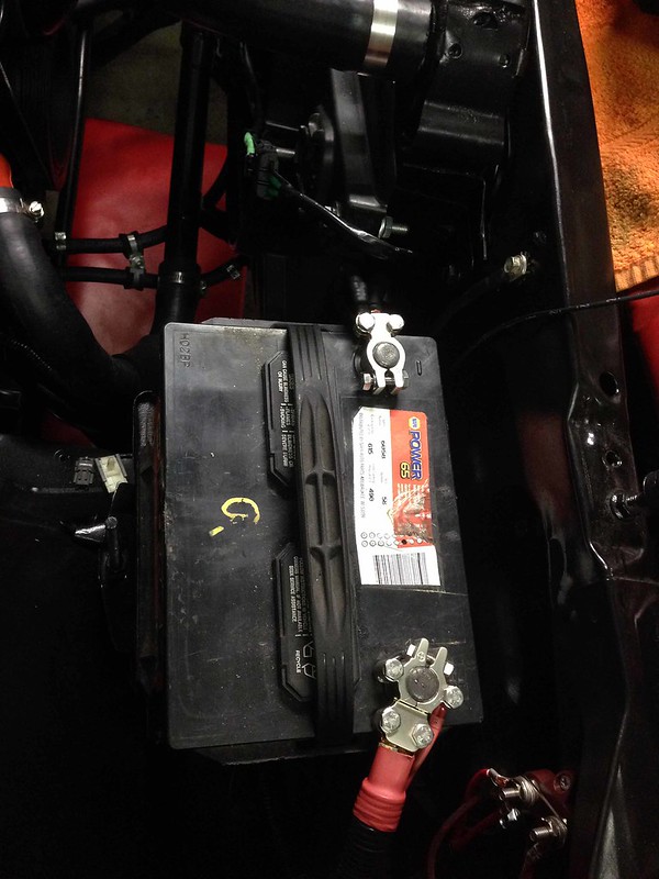
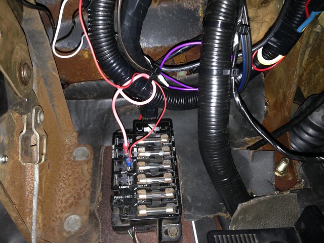
Detailed shot of the battery +ive distribution post arrangement...
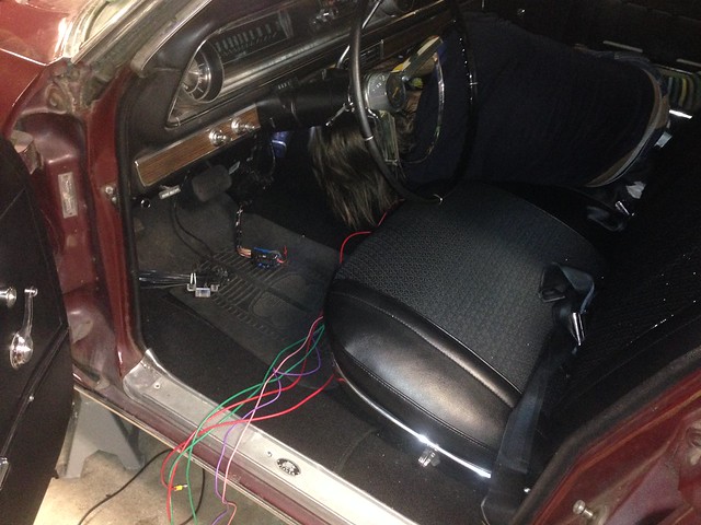
Secondly: Wire the fuel pump (purple 4mm wire). We ran the wire under the carpet (down the passenger side of the car), under the base of the seat and dragged it though into the boot using floor board tongue...
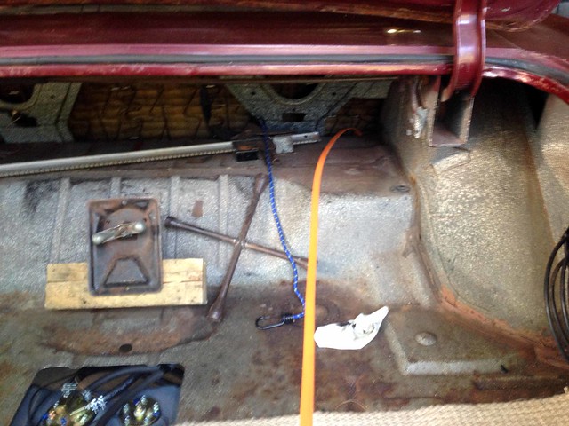
From there we passed it under the car, through a re-purposed grommet (that was used for the old fuel tank vent), up to the fuel pump and terminated.
Third task takes place under the dash (hard to take photos as the wiring is so well hidden!):
Wire a starter relay which is conditioned to feed the starter solenoid only when the trans is in Park or Neutral (managed by the ECU... the existing Chev P/N switch is by-passed).
We grabbed a relay from one of the VZ relay blocks and mounted into a relay base that clipped to the end of the string of relays in the ECU harness.
existing Chev start trigger wire = pin 86
grey 2mm wire from ECU = pin 85 (switched ground).
existing Chev start trigger wire = pin 30 (looped from the feed to pin 86)
wire to starter solenoid = pin 87
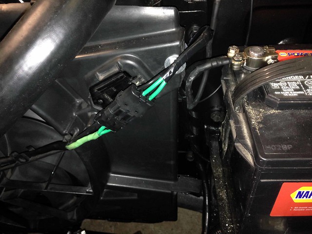
Fourth: Wire the thermo fan (green 2 x 5mm wires).
More tomorrow.
J
Through the week I booked the exhaust for 9/12 and rego inspection for 12/12, so there is a real urgency now to knock-off the last items on the to-do list... the majority being related to keeping smoke within wires.
We had mini working bee Tue night to fit the battery tray and drill through the firewall on the passenger side for battery positive, thermo fan and starter wires.
During the week, various parts were acquired ready for a committed weekend of wiring...
- 25 mm2 cable (battery to starter, batter to alt, ground)
- lugs for 25mm2 cable
- distribution post for feeding battery +ive to various circuits
- relay base (will reuse a relay from the VZ for P/N start conditioning)
- plug for thermo fan connection
- 10mm dia split conduit
- 16mm dia split conduit
So to the weekend: a HUGE double header from JtC, making the trip north on both Sat (wiring till midnight) and Sun in an attempt to get the beast started.
First mission:
- Create new battery/ground cables.
- Wire the battery positive/starter/alternator/ground harness.
- Wire the existing Chev battery positive harness to the existing horn relay.
- Wire constant power source (red 2 x 6mm wires) from EFI to battery positive...
Detailed shot of the battery +ive distribution post arrangement...
Secondly: Wire the fuel pump (purple 4mm wire). We ran the wire under the carpet (down the passenger side of the car), under the base of the seat and dragged it though into the boot using floor board tongue...
From there we passed it under the car, through a re-purposed grommet (that was used for the old fuel tank vent), up to the fuel pump and terminated.
Third task takes place under the dash (hard to take photos as the wiring is so well hidden!):
Wire a starter relay which is conditioned to feed the starter solenoid only when the trans is in Park or Neutral (managed by the ECU... the existing Chev P/N switch is by-passed).
We grabbed a relay from one of the VZ relay blocks and mounted into a relay base that clipped to the end of the string of relays in the ECU harness.
existing Chev start trigger wire = pin 86
grey 2mm wire from ECU = pin 85 (switched ground).
existing Chev start trigger wire = pin 30 (looped from the feed to pin 86)
wire to starter solenoid = pin 87
Fourth: Wire the thermo fan (green 2 x 5mm wires).
More tomorrow.
J
Sunday, 20 November 2016
Intake + Thermo Fan Finalised
The most annoying work is having to do work a second time. This was what was before us in having to remove the Commodore thermo fan and start the mounting process from scratch with the Falcon fan.
JtC made the trip up and got stuck in.
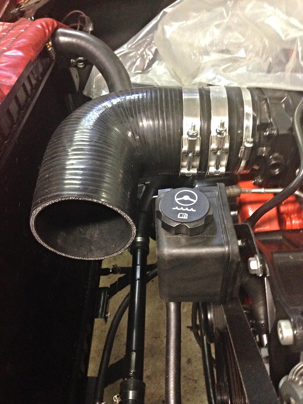
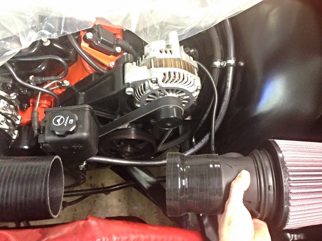
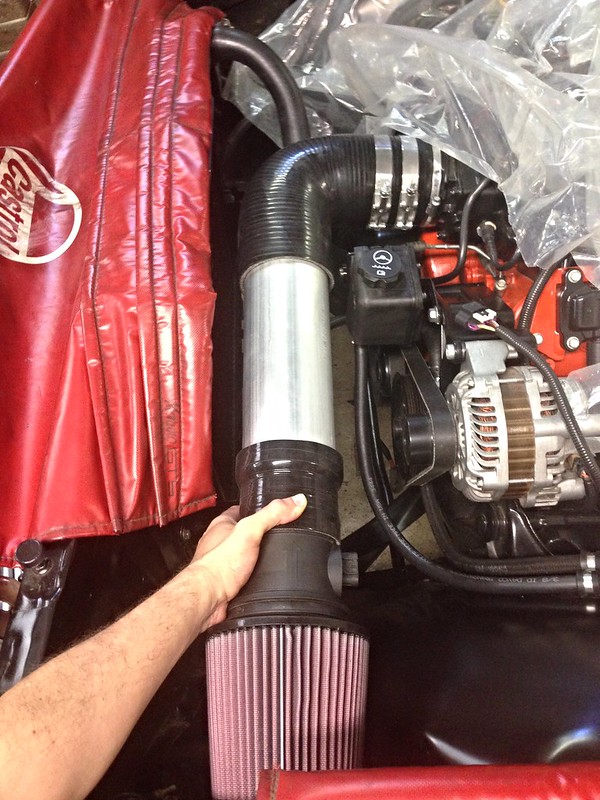
Thankfully, it was more material removal required than making a shroud. The Falcon fan sat well, hard against the radiator core with a slim profile, allowing the intake pipe to thread its way between the radiator and the power steeering reservior...
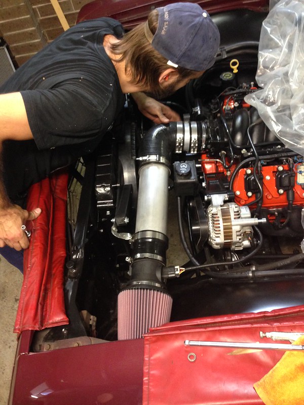
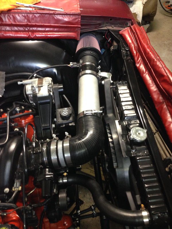
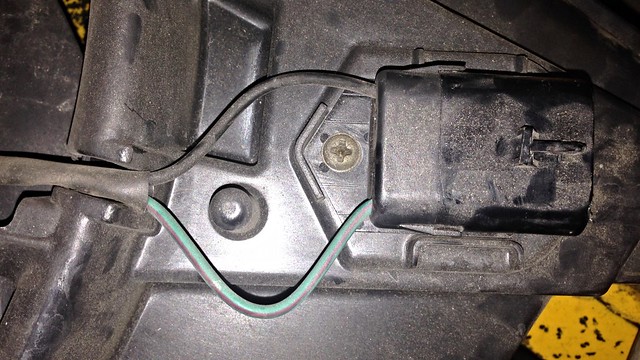
The MAF/pod filter assembly is supported and held in position by a bracket off the radiator support.
Note the exposed length of alloy pipe at the throttle body inlet.
Clearance everywhere... a work of art!
BIG thanks to JtC in enduring the pain of doing a task twice-over, all the while taking his time to do it right!
J
P.S.
While inlet + thermo fan was happening, I wire-brushed and painted the battery tray ready for refitting.
JtC made the trip up and got stuck in.
Thankfully, it was more material removal required than making a shroud. The Falcon fan sat well, hard against the radiator core with a slim profile, allowing the intake pipe to thread its way between the radiator and the power steeering reservior...
The MAF/pod filter assembly is supported and held in position by a bracket off the radiator support.
Note the exposed length of alloy pipe at the throttle body inlet.
Clearance everywhere... a work of art!
BIG thanks to JtC in enduring the pain of doing a task twice-over, all the while taking his time to do it right!
J
P.S.
While inlet + thermo fan was happening, I wire-brushed and painted the battery tray ready for refitting.
P.S.S.
The photos above were taken before the steam pipe was connected, but JtC connected it as well <phew>!
Thursday, 17 November 2016
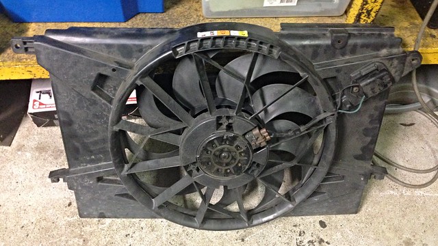
Four Letter F-word
So the original plan to use a thermo fan from a VS V6 Commodore (see here) wasn't going to work.
Once we started dummying-up the intake, it soon became obvious that the massive shroud over the top of the VS fan was going to foul the pipe to the throttle body.
After a bit of research, it was decided to go with a thermo fan from the dark side... a big single from a FG Falcon...
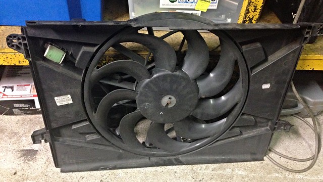
J
Once we started dummying-up the intake, it soon became obvious that the massive shroud over the top of the VS fan was going to foul the pipe to the throttle body.
After a bit of research, it was decided to go with a thermo fan from the dark side... a big single from a FG Falcon...
J
Sunday, 13 November 2016
Intake
Time to turn our thoughts to the intake...
Short piece of silicon hose and alloy pipe off the throttle bode to ensure the 90 degree bend could clear the power steering reservoir.
The more astute reader will notice the missing radiator fan.
Clearing the power steering reservoir meant the huge shroud of the V6 Commdore thermo fan we had installed a couple of weeks prior was now going to foul the intake <sigh>.
Solution to that little issue next post.
The good news is the top radiator hose I sourced here, worked a treat (with a bit of judicial trimming)!
Trialing the MAF/pod position...
Dummied-up...
This will be the final position of the pod/MAF, with some tweaks to be made to the reducer section length (4" section too short... swapped for a longer one), and exposing some of the alloy pipe at the throttle body (by reducing the 90 deg. bend leg length).
J
Monday, 7 November 2016
Wiring
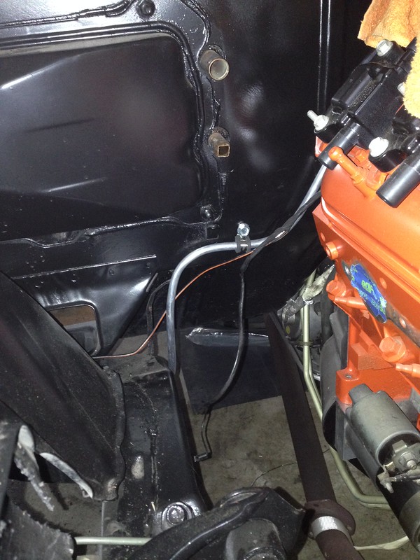
A few days after the hole in the firewall was finished, JtC came up to help pull wires through...


Acres of room under a full-size dash for mounting all the paraphanalia!
We'll leave the harness, ECU's, etc. hanging down for access while we wire.
J
Friday, 28 October 2016
New Tailshaft
New thicker-wall tailshaft (80 mm shorter than original to accomodate the longer 4L65E) and new uni joints, packed with grease ready to be bolted-up...
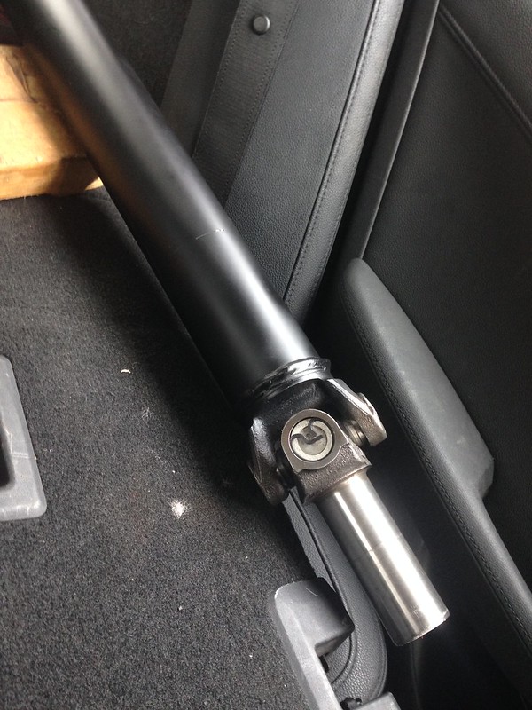
Work done by A&L Driveshafts in Campsie.
UPDATE: exploded on the dyno on Tue 17.04.2018.
The A&L driveshaft was 2.750" OD with 0.083" wall... waaay too small!
J
Work done by A&L Driveshafts in Campsie.
UPDATE: exploded on the dyno on Tue 17.04.2018.
The A&L driveshaft was 2.750" OD with 0.083" wall... waaay too small!
J
Thursday, 27 October 2016
The small things in life
The steam pipe outlet on the LS needs a 6 mm ID hose.
The inlet port to the top tank of the radiator needs a 10 mm ID hose.
Get both size hoses and join in the centre with this...
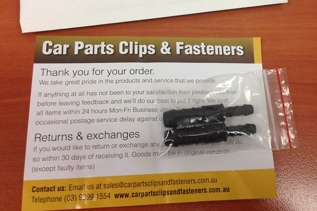
One required but bought two in case one snapped ;-)
J
The inlet port to the top tank of the radiator needs a 10 mm ID hose.
Get both size hoses and join in the centre with this...
One required but bought two in case one snapped ;-)
J
Tuesday, 18 October 2016
CSI: Radiator Hose Unit
---------- Forwarded message ----------
From: John
Date: Tue, Oct 18, 2016 at 11:00 PM
Subject: CSI: Radiator Hose Unit
To: JtC
From: John
Date: Tue, Oct 18, 2016 at 11:00 PM
Subject: CSI: Radiator Hose Unit
To: JtC
1.
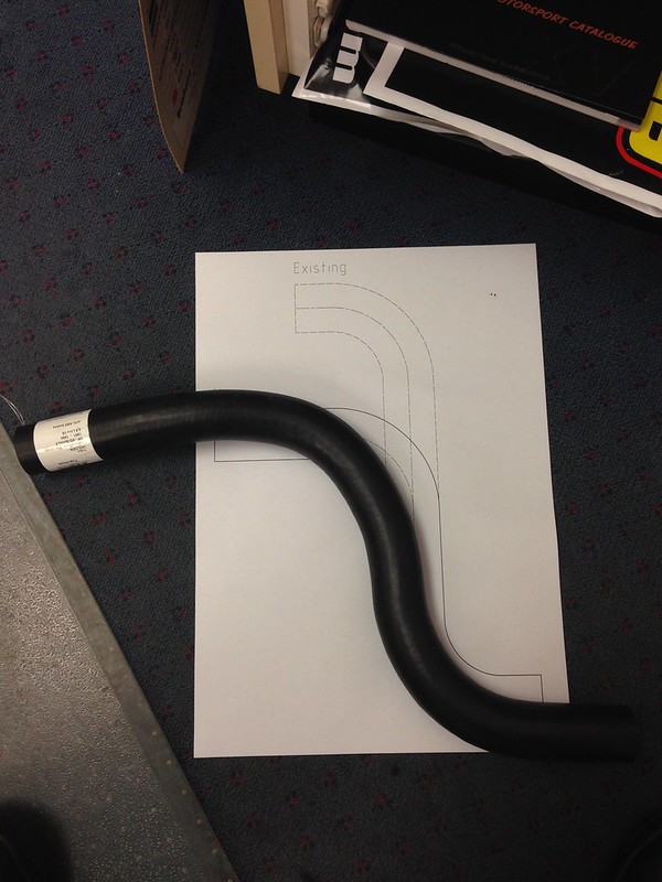
After a bit of measuring down in the garage, the attached "Top Radiator Hose Drawing" is going to be in the ball-park of what we are looking for. Printed out on A3 will give me a 1:1 template I can take with me to a parts store.
2.
Mackay Automotive have put out an AWESOME catalog which lists their hoses by ID, then length...
The top hose needs to be 33 mm ID. There looks to be a few which are promising, with CH1848 one of the best (with some trimming to length).
3.
Did a quick search for CH1848 on Supercheap Auto's website...
Now to go have a look!
It just happens to be the top radiator hose off a V6 VN-VR with ABS... did you salvage the top hose off the VR you bought?
J
Other promising ones...
---
Mackay
33 mm ID x 424 mm long as the basis...
---
CH3420
CH3539
CH3730
CH4822
CH1368
CH2552
CH3336
CH4274
CH3900
CH4009
CH1365
CH4954
CH1848 <-- 05-0922 <-- 92046089
Monday, 3 October 2016
Headers + Engine Pipes
Grit blast the headers...
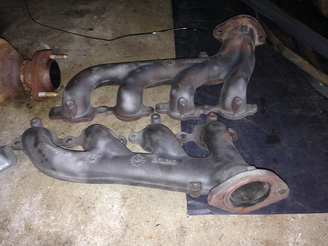
Quick wipe down with wax and grease remover.
Hit with this...
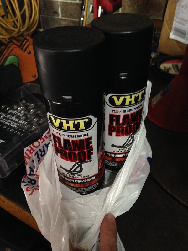
..."in" the outdoor spray booth...
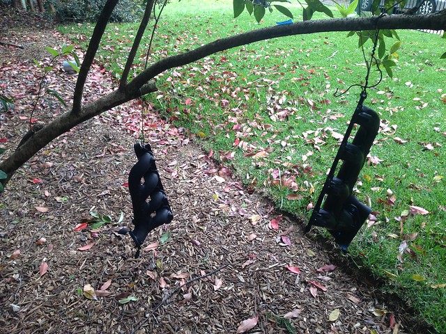
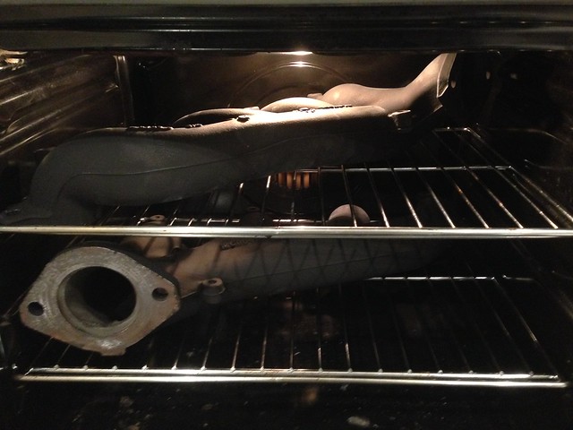
...and baked to perfection...
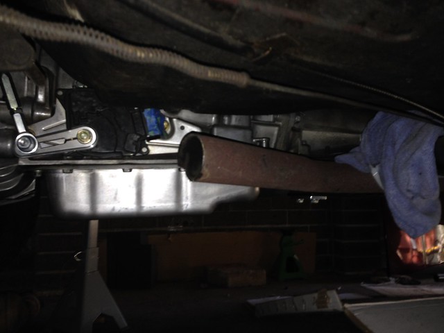
Back under the car, JtC axed through the engine pipes, just forward of the trans cross member...
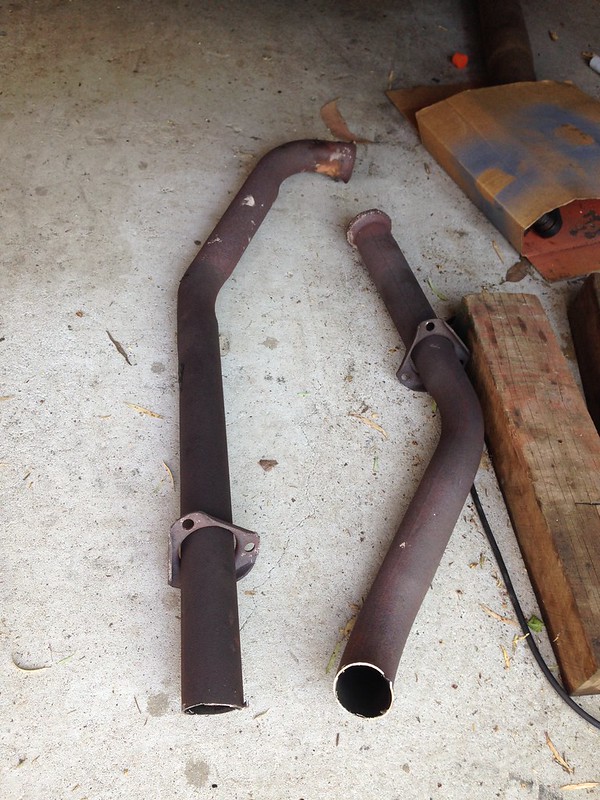
He then tied the exhaust to the transmission cross member ready for the transport (drive!?) to the exhaust shop...
J
Quick wipe down with wax and grease remover.
Hit with this...
..."in" the outdoor spray booth...
...and baked to perfection...
Back under the car, JtC axed through the engine pipes, just forward of the trans cross member...
He then tied the exhaust to the transmission cross member ready for the transport (drive!?) to the exhaust shop...
J
Wednesday, 28 September 2016
Radiator and Thermo Fan Clearance Dimensions
Scratch below! We are deleting the spacer (decided 02.10.2016).
From: John
Date: Wed, Sep 28, 2016 at 12:08 PM
Subject: Radiator and Thermo Fan Clearance Dimensions
To: JtC
See here...
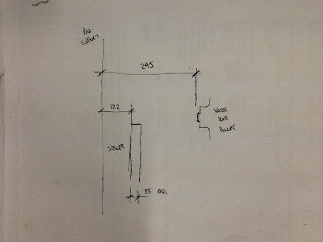
So spacer + radiator = 122 mm + 55 mm = 177 mm.
Radiator support to water pump pulley is 245 mm.
That gives an absolute maximum radiator width of 63 mm (which only leaves 5 mm to the water pump).
Now... Summit has a nice search feature where you can search by thickness of thermo fan.
It looks like there are a few options:
The 2.000" and 2.031" versions look like the go.
The other factor to keep in mind is the hose lengths. That will be another factor in keeping/omitting the spacer.
J
Sunday, 18 September 2016
Fuel Hard Line
Went into this little project with a degree of apprehension... running the fuel feed hard line from the rear of the car to the front.
I experimented with a length of tube out of the VZ. OK, but a bit tough to bend and the real concern was routing over the rear axle, as well as bending up into the engine bay.
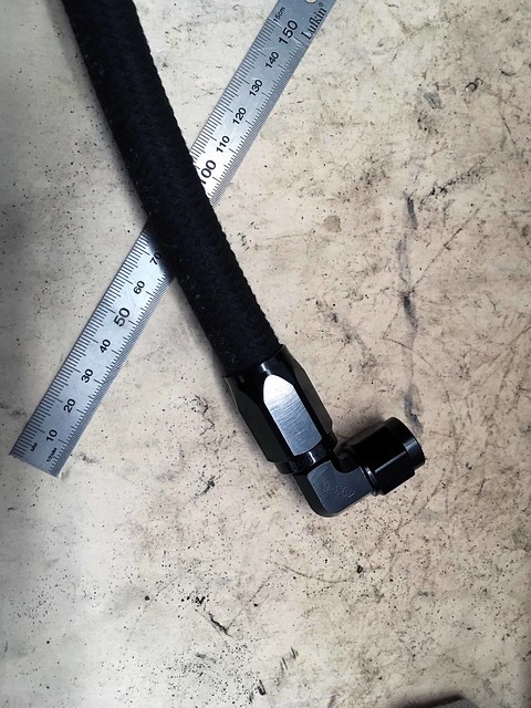
But first, some new shiny bits...
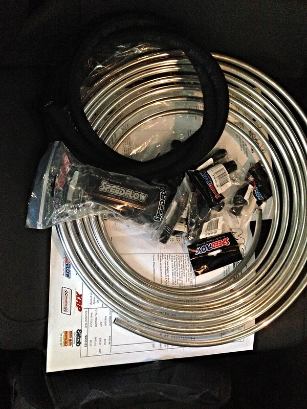
The black hose is for the power steering high pressure line from the pump to the steering box (another story). For today, we are concentrating on the coil of new 3/8" tubing and Speedflow hardline adaptors.
So the plan is...
GM female 3/8" QD on the filter output...
-> Speedflow GM 3/8" EFI adaptor to male AN-6 (716-06-06-BLK)
-> Speedflow male AN-6 to female AN-6 3/8" hardline adaptor (619-06-06-BLK)
-> Speedflow 3/8" hardline
-> Speedflow female AN-6 3/8" hardline adaptor (619-06-06-BLK)
-> Speedflow GM 3/8" EFI adaptor to male AN-6 (716-06-06-BLK)
-> fuel hose from the VZ.
Time to get JtC on the case...
Without seeing the job, there were no concerns.... easy!
Once on a creeper and under the car, the bend over the axle and the bends into the engine bay weren't looking so easy.
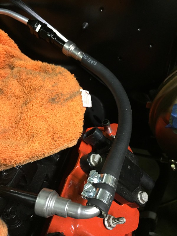
The decision was made to butcher the VZ fuel hose and make our own EFI rubber hose with the GM quick disconnect fittings to run from the engine, down to the chassis rail. Then it would be hard line to the axle where we would swap back to flexible hose for the axle bend.
A plan!
For a bit of laugh, JtC thought he would have a quick try bending the Speedflow hard line up and over the axle.
We shouldn't have been concerned, the new hard tubing was a lot more flexible and easier to work with than the original Holden lines.
Next minute... hard line routed over the axle, over the trans cross member, even clipped into the original Chev retaining clips...
We were able to un-spool the coil of tubing up and into the engine bay, retaining the tubing with P-clips...
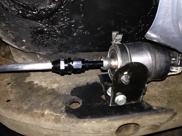
A thing of beauty!
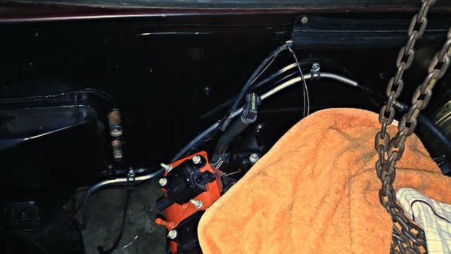
Because we butchered the VZ fuel hose to the engine, we had to recreate it with EFI rubber hose. Here it is waiting for two more EFI hose clamps (what a time to run out)...
BIG thanks to JtC for weaving his car whispering magic once again!
J
I experimented with a length of tube out of the VZ. OK, but a bit tough to bend and the real concern was routing over the rear axle, as well as bending up into the engine bay.
But first, some new shiny bits...
The black hose is for the power steering high pressure line from the pump to the steering box (another story). For today, we are concentrating on the coil of new 3/8" tubing and Speedflow hardline adaptors.
So the plan is...
GM female 3/8" QD on the filter output...
-> Speedflow GM 3/8" EFI adaptor to male AN-6 (716-06-06-BLK)
-> Speedflow male AN-6 to female AN-6 3/8" hardline adaptor (619-06-06-BLK)
-> Speedflow 3/8" hardline
-> Speedflow female AN-6 3/8" hardline adaptor (619-06-06-BLK)
-> Speedflow GM 3/8" EFI adaptor to male AN-6 (716-06-06-BLK)
-> fuel hose from the VZ.
Time to get JtC on the case...
Without seeing the job, there were no concerns.... easy!
Once on a creeper and under the car, the bend over the axle and the bends into the engine bay weren't looking so easy.
The decision was made to butcher the VZ fuel hose and make our own EFI rubber hose with the GM quick disconnect fittings to run from the engine, down to the chassis rail. Then it would be hard line to the axle where we would swap back to flexible hose for the axle bend.
A plan!
For a bit of laugh, JtC thought he would have a quick try bending the Speedflow hard line up and over the axle.
We shouldn't have been concerned, the new hard tubing was a lot more flexible and easier to work with than the original Holden lines.
Next minute... hard line routed over the axle, over the trans cross member, even clipped into the original Chev retaining clips...
We were able to un-spool the coil of tubing up and into the engine bay, retaining the tubing with P-clips...
A thing of beauty!
Because we butchered the VZ fuel hose to the engine, we had to recreate it with EFI rubber hose. Here it is waiting for two more EFI hose clamps (what a time to run out)...
BIG thanks to JtC for weaving his car whispering magic once again!
J
Saturday, 3 September 2016
Pity the Fuel!
New parts coming in thick and fast...
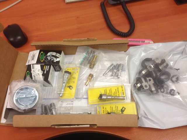
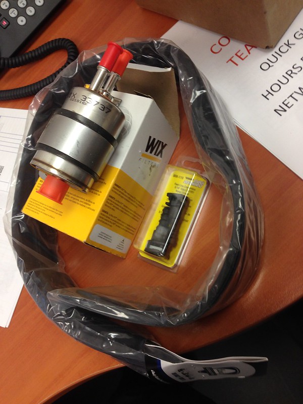
...time to install.
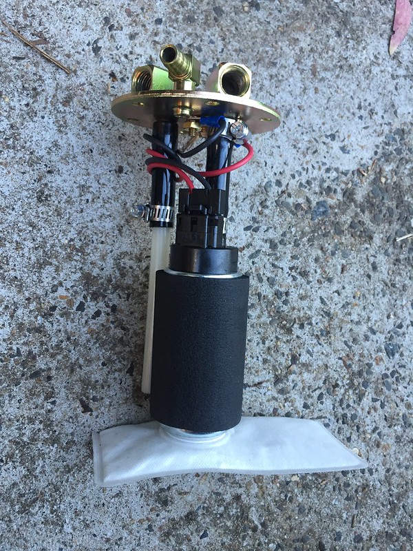
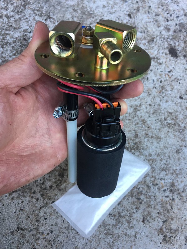
The pump outlet/return ports are female 1/4" NPT, so a couple of 3/8" barb adapter fittings will go there with Gates Barricade 3/8" EFI hose double clamped to the barbed fittings.
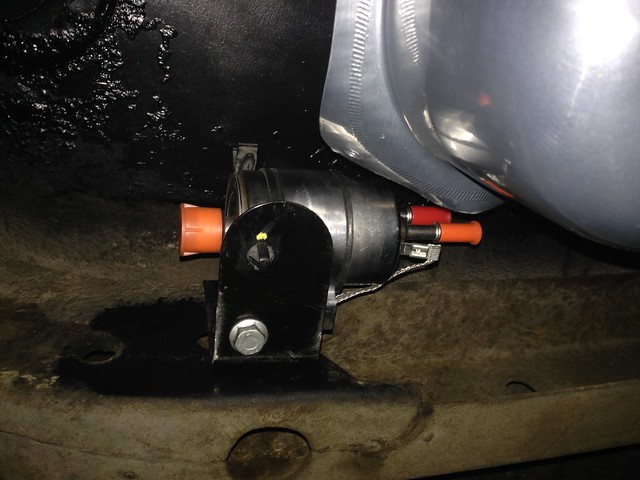
I have gone with a Corvette regulator/filter which takes care of regulating the fuel pressure, as well as the return to the tank, so only one 3/8" line needs to be run to the engine.
The filter/reg has a male 3/8" quick connect entry and a male 5/16" quick connect return. Feed to the filter uses a Dorman 3/8" quick connector double clamped to the feed hose.
Because I have a heap of 3/8" hose, I wanted to use that for the return as well so used a Dorman 5/16" quick release to 3/8" barb adapter.
Not sure what the result will be, clamping hose to a nylon fitting where normally nylon hose would be used... we'll see.
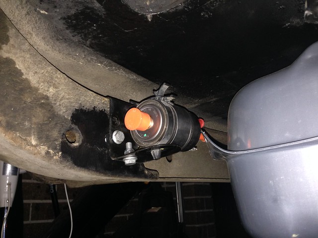
Anyhows, running the lines is to come. First: mounting the filter.
Waste not, want not: the VZ Commodore fuel filter bracket was resurrected...
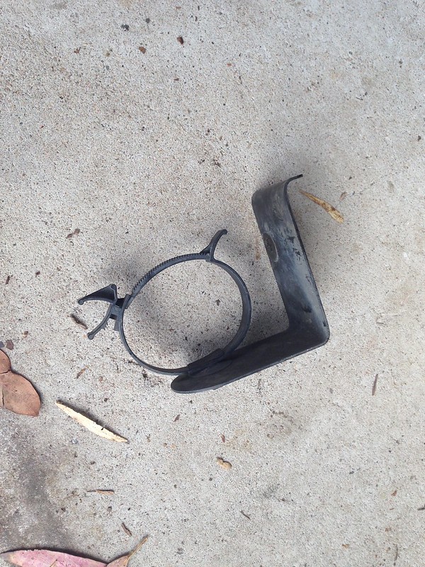
...and pushed into service...
Plumbing to come!
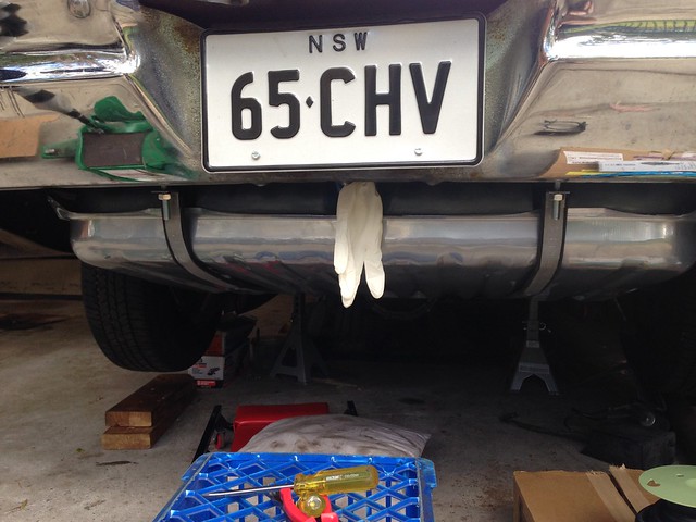
Ooo... almost forgot! Fuel tank went in with the rubber-lined straps...
J
...time to install.
The pump outlet/return ports are female 1/4" NPT, so a couple of 3/8" barb adapter fittings will go there with Gates Barricade 3/8" EFI hose double clamped to the barbed fittings.
I have gone with a Corvette regulator/filter which takes care of regulating the fuel pressure, as well as the return to the tank, so only one 3/8" line needs to be run to the engine.
The filter/reg has a male 3/8" quick connect entry and a male 5/16" quick connect return. Feed to the filter uses a Dorman 3/8" quick connector double clamped to the feed hose.
Because I have a heap of 3/8" hose, I wanted to use that for the return as well so used a Dorman 5/16" quick release to 3/8" barb adapter.
Not sure what the result will be, clamping hose to a nylon fitting where normally nylon hose would be used... we'll see.
Anyhows, running the lines is to come. First: mounting the filter.
Waste not, want not: the VZ Commodore fuel filter bracket was resurrected...
...and pushed into service...
Plumbing to come!
Ooo... almost forgot! Fuel tank went in with the rubber-lined straps...
J
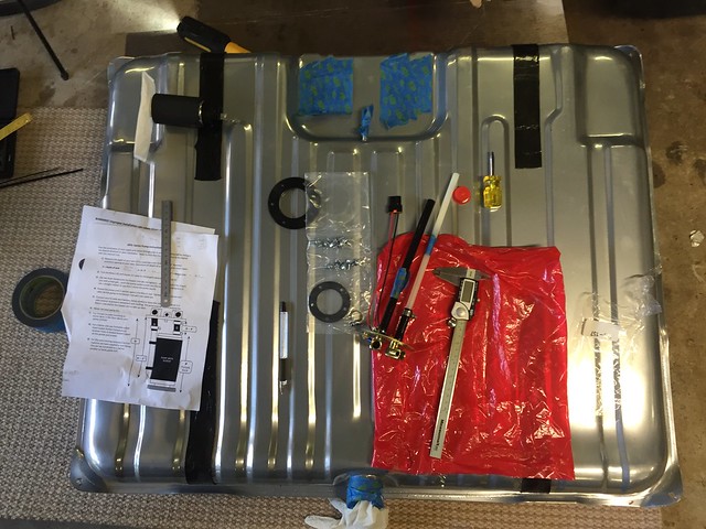
Saturday, 27 August 2016
More fuelling around...
During the week, more bits turned up...
More tank liner material, as well as some other bits that are for a later post.
JtC made the trip north to see what damage I had caused with the tank install.
First task: clad the tank straps with rubber liner.
As is so often the case, reproduction parts don't quite fit and for us the new straps were a smidge too wide for the strap liners.
Angle grinder time...
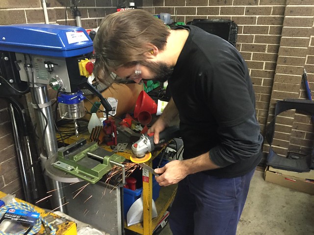
Voila!
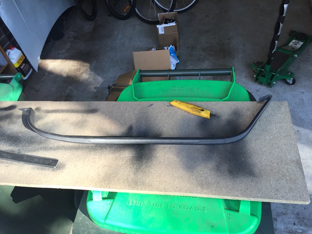
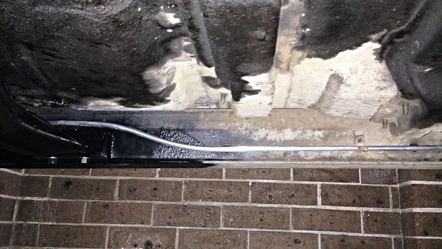
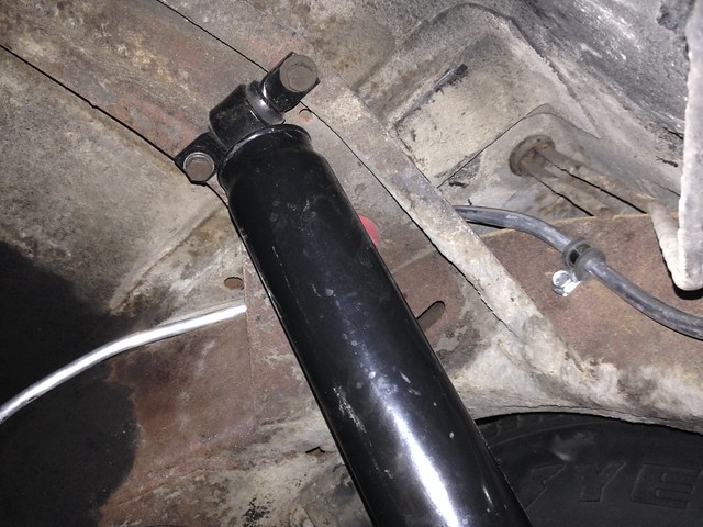
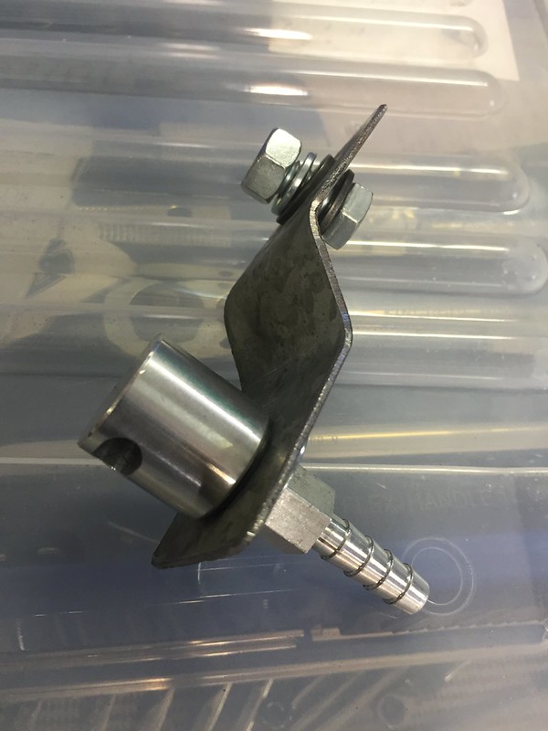
Next: mounting the tank vent/roll-over ball valve.
Bit of scrap gal steel bent into a z-bracket...
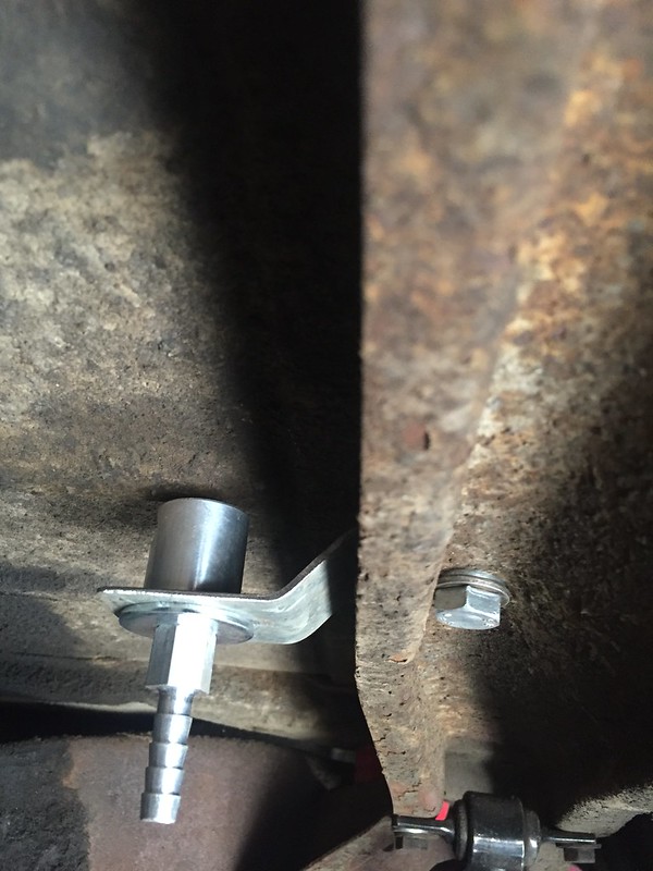
Bolted in place, on the brace that the rear shocks bolt to...
Finally: fitting the in-tank fuel pump and sender...
J
More tank liner material, as well as some other bits that are for a later post.
JtC made the trip north to see what damage I had caused with the tank install.
First task: clad the tank straps with rubber liner.
As is so often the case, reproduction parts don't quite fit and for us the new straps were a smidge too wide for the strap liners.
Angle grinder time...
Voila!
Next: mounting the tank vent/roll-over ball valve.
Bit of scrap gal steel bent into a z-bracket...
Bolted in place, on the brace that the rear shocks bolt to...
Finally: fitting the in-tank fuel pump and sender...
J
Subscribe to:
Posts (Atom)