Wednesday, 25 May 2016

Transmission Crossmember - Part 2

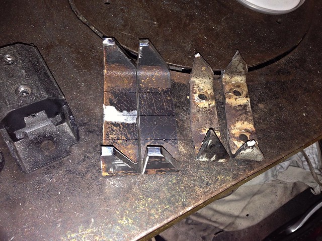
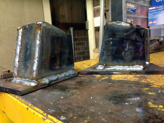
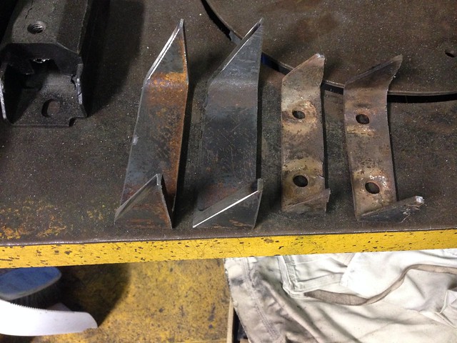
So, new on the left, old on the right...

Saddles 01

Saddles 02

The material is some scrap 125 PFC (parallel flange channel), pretty much perfect for my application!

The only downside is the PFC has very thick flanges (7.5 mm thick in this case). The nice part is that the web is 4.7 mm thick which is gold...


Welding to the chassis rail will be a bit interesting. I'll grind a bevel weld prep into the flange and do some test welds first to get the current setting right.

J

Thursday, 19 May 2016

Transmission Crossmember - Part 1

Buzzed the trans mount tongue off the tubular cross member last night at 9:30 PM (sorry neighbours).

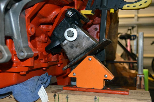
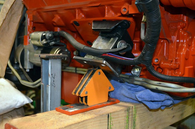
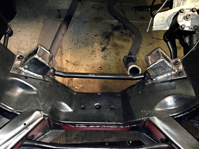
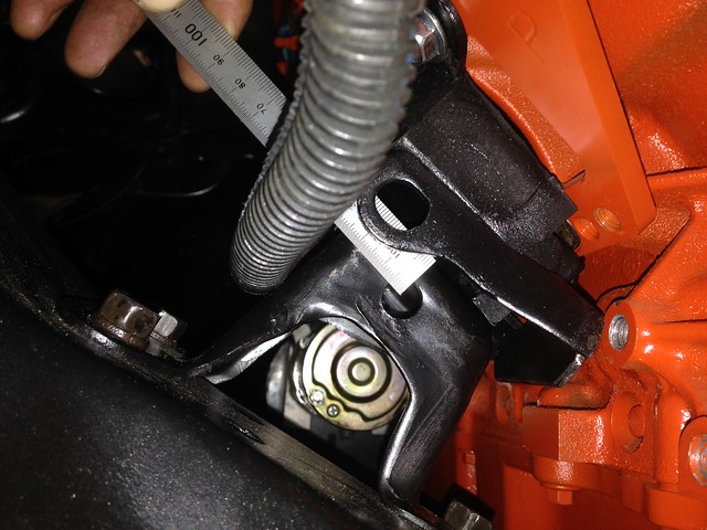
Unbolted the weird 90 degree bracket from the transmission mount, so now we have clear access behind the trans mount (attached is a photo).

The cross member can sit up under the snout of the trans, right where the axle stand is in the photo...


This would mean relocating the chassis saddles rearward to the tune of 200 mm.

We will need to lift the end of the trans 13 mm to get the tubular cross member under the snout. If my calcs are correct, it means reducing the angle of the engine/trans by one degree.

Should be fine. Now it is a case of checking the trans and diff angles, plus whether raising the end 13 mm fouls the transmission tunnel anywhere.

J

We may be able to reuse the existing crossmember, but would need to remove the black bracket off the trans engine mount.

It would be close re. exhaust.

What I might do is trim off the existing Powerglide mounting bracket on the crossmember because we need to change/relocate that anyway. Then I can lift the tube into place to see how it looks.

J

On Wed, May 18, 2016 at 10:51 AM, JtC wrote:
I am very keen to retain the x-member as-is, no mods if possible. Factory is always best & it's a nice looking thing.
Will the new gearbox mount drop into the old crossmember without any of it fouling on the curves of the xmember?
Will the dips for the exhaust still provide clearance in the correct places also?
Can we get the driveline angle right with the old Commodore mount arrangement? I think it's in two parts, we may just need to remove one part.
Sort out new handbrake cable situation. We actually needed to do that anyway.
I honestly think we will be able to simply relocate the old xmember forward/rearward as needed and then fiddle around with the mount height as needed with a little chopping and maybe a spacer or whatever.
From: John


The easiest method will be to relocate the existing chassis rail mounting saddles.

J

Saturday, 7 May 2016

Stuff

Sat was two hours spent mucking around getting the Chev up on stands. Pain of a job with the engine pipes getting in the way of everything to do with the trans. All good now and spent the time getting a setup which has good access. I turned the front wheels to help the passenger side engine pipe clear the steering link, then brought the chain block over and used fabric slings under the engine pipes to lift them up, it has worked really well and we now have a clear floor under the Chev. I have sat the end of the trans on one of my old ratchet stands with bricks/wood blocks under it to trim the height, so now it is an easy task to trim the gearbox level with the trolley jack as-required.

Sat night I bolted the ancillary drive bracket onto the engine. Looks good. The problem I had feared re. the power steering input was realised... it fouled the bracket/pulley.

Attached is a photo...


You can see the brass-coloured tube that is simply pushed into the pump housing, sealed with an o-ring and retained with the keeper plate you can see.

It needs to be clocked 90 degrees (and you'll notice a second keeper plate retaining bolt hole in the housing) but if you do, the tube hits the pulley. This isn't a problem, I simply bent the tube outwards using 2 x 3/8" extensions. But the second bolt hole is not tapped + mocking it up in the bracket, the keeper plate fouls the bracket in the clocked position.

So the next trick (and where I am up to) is to twist the tube in the keeper plate to maintain the keeper plate position, but have the tube pointing outwards at 90 deg.

J

Saturday, 30 April 2016

Finally In!

With the pedestals complete, it was time to try dropping the LS in for a second time.

We are old hands at the process and soon had the engine bolted up on one side... but no joy on the other with the mount holes out of alignment to the pedestal holes by 10 mm.

Soul-searching insued trying to figure out a) what went wrong and - more to the point - b) how to fix it.

The original Chev engine mounts had long slots in the mounting holes, so the decision was to lift the engine clear of the pedestals just enough to swap the mounts out.

Before we did, JtC opened up the slots a bit more to give us every opportunity of getting this sucker home to its final resting spot, while I ground down the pedestals (in situ) to ensure the mounts could sit low enough to get the holes to line-up.

Drill/file/grind/paint and - with the new modified arrangement - the 6.0L dropped in like Chev designed it!
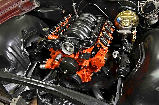
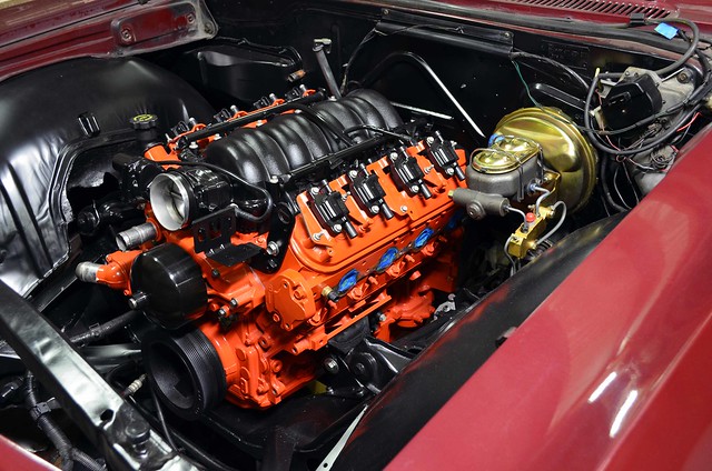
EngineIn03

EngineIn06


It turned out we didn't need to open the slots any further as the original mounts lined-up better than the reproduction items!

My dents in the trans tunnel were enough to clear the transmission servo.

Bolting the engine mounts in the next location forward on the adapter plates has set the engine back enough in the engine bay to ensure the exhaust now dumps behind the steering linkages.

This is a massive moment in the project and HUGE thanks to JtC for making the trip up and making the magic happen!

Next: gearbox crossmember.

J
Saturday, 23 April 2016

Done!

Welds relieved where required to clear the washers and cleaned-up.

Engine mount holes drilled after mocking-up the pedestals to the LS...

Driver's Side Mocked-up

Passenger's Side Mocked-up

J

Thursday, 21 April 2016

Sitting in their new home...

Located in place


Just need to:
- relieve the welds in 2 x spots to clear the washers,
- drill the engine mount bolt holes to suit the final location of the engine,
- final clean up of the welds and...
- hit with a coat of satin black.

Gettin' close to engine test fit #2!

J

Fwd: Ramblings

From: John
Date: Thu, Apr 21, 2016 at 11:00 AM
Subject: Ramblings
To: JtC

Yeah, so straight away I could tell the old gas bottle was empty... the new one weighs a ton!

Got it home and cracked the valve for 0.01 seconds... I don't think I have any hearing left ;-)

Welding went ok. Won't win any beauty contests, but doesn't look too bad. It is beyond rock-solid and is all sealed up...

Seam Welded


This morning, before work, I spent less than 10 mins seeing how the welds would clean up on the grinder. Not bad! See below...


I will need to touch the weld across the front of the SHS in one spot with the grinder to make sure the washer clears.

Immediate list:
- final clean-up of the welds with a grinder
- drill base holes
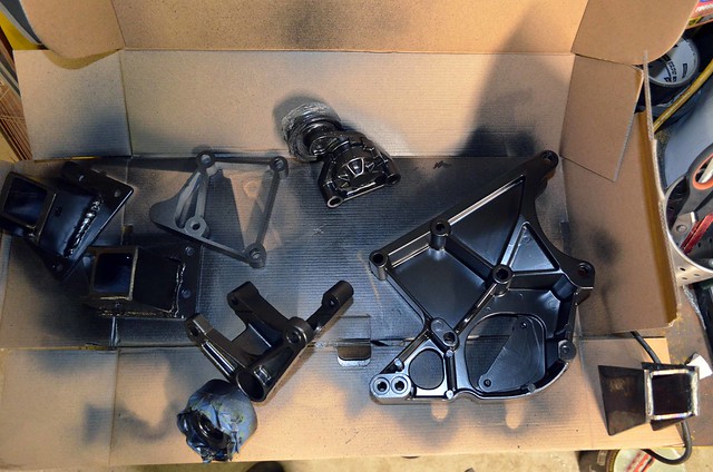
- paint pedestals + Holley ancillary brackets black
- locate pedestals on cross member
- make up a jig to pick-up the location of engine mounts
- drill engine mount holes in pedestals
- bolt pedestals to cross member
- drop engine in!

J

Saturday, 16 April 2016

Fabricating New Engine Mount Pedestals

The engine test-fit on 29.03.2016 showed that the engine mounts didn't quite meet the pedestals that are bolted to the cross member...

Untitled


The original plan was to make packer plates between the mounts and adapter plates, to move the engine mounts closer to the pedestals.

That idea was ditched as I wasn't confident the holes would line-up across the car.

Plan B: fabricate new pedestals!

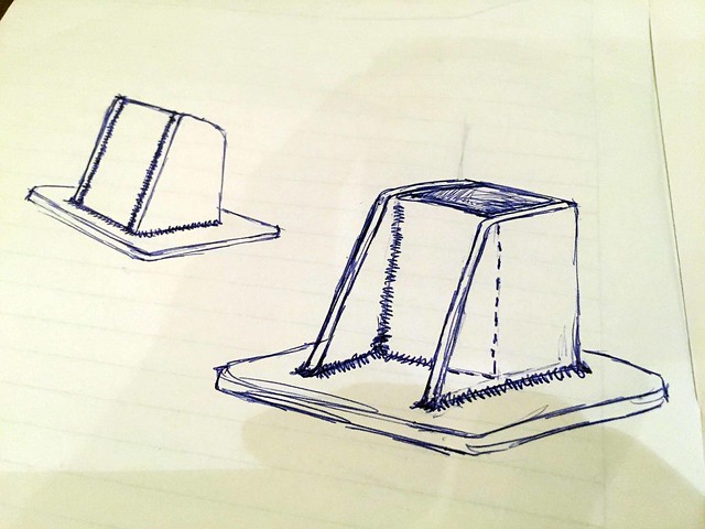
I drafted a few designs before JtC tweaked my penultimate design for this - final - concept...

Sketch


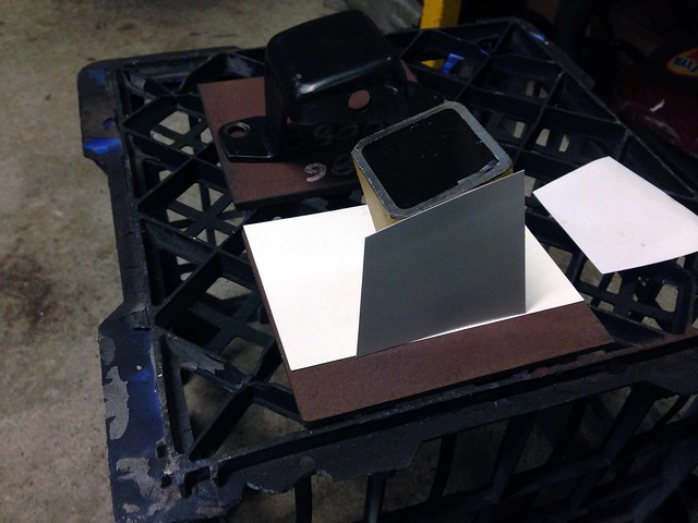
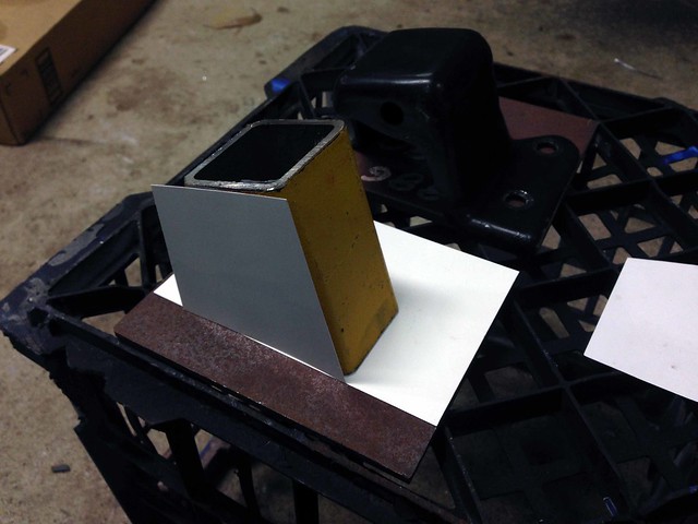
Back to AutoCAD to tweak the design. It wasn't long before some 1:1 templates were printed and cut out of card...

Templates

Templates


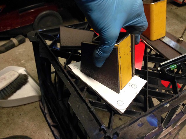
Plate was cut and the final design mocked-up in steel...

Mock-up


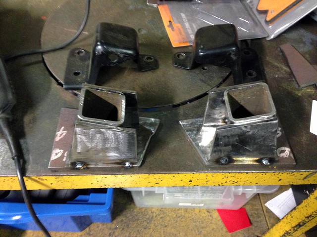
New vs. old. Tacked ready for seam welding...

Tacked

Material:
50 x 50 x 4.0 SHS
6 PL

J